07/12/19
Message Overview:
| DDG Reference: | None |
| Pilot Action (QRH): | ELEC 04-26 |
| System Description: | 24-31-00 |
| Schematic Diagram: | 24-31-00 [ Global Express ] [ G5000 ] [ Global XRS ] |
| Wiring Diagram: | 24-31-02 [ Global Express ] [ G5000 ] [ Global XRS ] |
Fault Description:
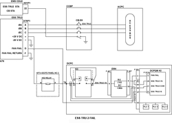
DC Power Quality Monitor #2 in the DCPC is reporting that the ESS TRU 2 has failed.
Possible Causes:
- Essential Transformer Rectifier Unit (ESS TRU) 2 (A76)
- ACPC Electronic Module 4 (EM4)
- DC Power Quality Monitor (DCPQM) 2
- DC Power Center (DCPC) (A63)
- Associated Wiring
Troubleshooting Tips:
Advisory Wire/Service Bulletin: None
Forum Articles/Infoservice/Newsletter: None
NOTE: If the TRU is still producing voltage and the TRU is outlined in an amber box on the DC electrical synoptic page, suspect a defective TRU fan.
NOTE: If the TRU voltage indication on the DC synoptic page is less than 26 volts, suspect a bad or a missing input phase from the Alternative Current (AC) system.
Quick Links:
| Removal of the Transformer Rectifier Units | AMM 24-31-01-000-801 [ Global Express ] [ G5000 ] [ Global XRS ] |
| Installation of the Transformer Rectifier Units | AMM 24-31-01-400-801 [ Global Express ] [ G5000 ] [ Global XRS ] |
| Removal of the DC Power Center (DCPC) | AMM 24-61-00-000-801 [ Global Express ] [ G5000 ] [ Global XRS ] |
| Installation of the DC Power Center (DCPC) | AMM 24-61-00-400-801 [ Global Express ] [ G5000 ] [ Global XRS ] |
| Removal of the DC Power Center (DCPC) DC Power Quality Monitor | AMM 24-61-13-000-801 [ Global Express ] [ G5000 ] [ Global XRS ] |
| Installation of the DC Power Center (DCPC) DC Power Quality Monitor | AMM 24-61-13-400-801 [ Global Express ] [ G5000 ] [ Global XRS ] |
| Removal of the DC Power Center (DCPC) Electronic Modules | AMM 24-61-65-000-801 [ Global Express ] [ G5000 ] [ Global XRS ] |
| Installation of the DC Power Center (DCPC) Electronic Modules | AMM 24-61-65-400-801 [ Global Express ] [ G5000 ] [ Global XRS ] |
| Wire Repair - Maintenance Practices - ALL | SPM 20-12-10-02 [ Global Express ] [ G5000 ] [ Global XRS ] |
Troubleshooting Recommendations:
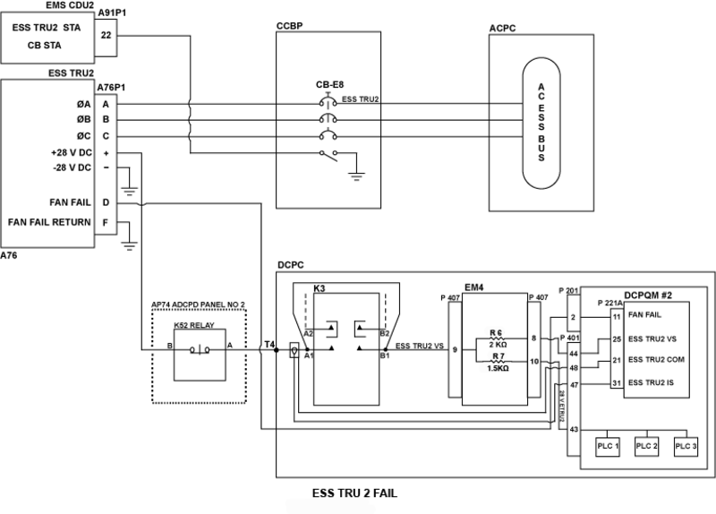
- Remove ESS TRU 2. Perform an 115 VAC voltage check on all three input phases (A76P1 pins A, B & C).
- If one or more input phase does not have adequate voltage, troubleshoot upstream and rectify as required.
- If all phases have adequate voltage, continue with next step.
- Swap ESS TRU 2 with TRU 2. Make sure that ESS TRU 2 is fed by an AC BUS. Is the ESS TRU 2 FAIL CAS message still displayed?
- If YES, continue with next step.
- If NO, replace defective TRU.
- Do a continuity check between ESS TRU 2 and the DCPC as follows:
From To Result ESSTRU2+ DCPC-T4 ESSTRU2- Ground - If there is continuity, continue with next step.
- If there is no continuity, repair defective wiring as required.
- Disconnect ESS TRU 2 connector A76P1. Access the DCPC logic assembly. Swap DCPQM 2 with DCPQM 1. Is the ESS TRU 2 FAIL message still present?
- If YES, continue with next step.
- If NO, replace defective DCPQM.
- Disconnect EM4 P407. Remove DCPQM 2. Do a continuity check as follows:
From To Result DCPC-T4 P407-9 P407-8 P221A-25 - If there is continuity, continue with next step.
- If there is no continuity, replace the DCPC.
- Do a continuity check as follows:
From To Result P407-9 Ground P407-8 Ground - If there is continuity, replace DCPC.
- If there is no continuity, continue with next step.
- Do a resistance check on EM4 as follows:
From To Expected Result Result J407-9 J407-8 2 KΩ J407-9 J407-10 1.5 KΩ - If measured resistance is good, continue with next step.
- If measured resistance is not good, replace EM4.
- Replace the DCPC.
- Do close out.