

07/24/25
Message Overview:
| DDG Reference: | None |
| Pilot Action (QRH): | HYD 11-5 |
| System Description: | 29-30-00 - Indicating |
| Schematic Diagram: | 29-13-00 [ Global Express ] [ G5000 ] [ Global XRS ] |
| Wiring Diagram: | 29-00-05 [ Global Express ] [ G5000 ] [ Global XRS ] |
Message Description:
The temperature of the hydraulic fluid of the No. 3 hydraulic system is above 205°F (96°C).
Possible Causes:
- Reservoir Hydraulic Fluid quantity is low.
- Low Fuel Level in the Left Wing Feed Fuel Tank
- Hydraulic Pumps (ACMP 3A/3B)
- Hydraulic Fluid Filter Elements are clogged
- Open Pressure Relief Valve in the Filter Manifold
- Hydraulic Heat-Exchanger Bypass-Valve
- Hydraulic System 3 Reservoir Temperature Transducer
- Hydraulic System 3 Reservoir
- Hydraulic Reservoir may have bypass
- Manifold may have bypass
- Heat Exchanger Bypass Valve
- Data Acquisition Unit (DAU) 3
- Associated Wiring
Troubleshooting Tips:
Advisory Wire/Service Bulletin: None
Full Throttle Blog/Forum Articles/Infoservice/Newsletter: None
Flight Operation Notifications Manual (FONM): None
NOTES:
- When replacing the pressure filters, a hydraulic lock has been known to prevent new filter installation. A "B" nut next to the filter manifold may need to be loosened or removed to bleed off pressure and allow the installation of the filter.
Quick Links:
| Removal of the No. 1 and No. 2 Hydraulic System Reservoirs | AMM 29-12-25-000-801 [ Global Express ] [ G5000 ] [ Global XRS ] |
| Installation of the No. 1 and No. 2 Hydraulic System Reservoirs | AMM 29-12-25-400-801 [ Global Express ] [ G5000 ] [ Global XRS ] |
| Removal of the No. 3 Hydraulic System Reservoir | AMM 29-13-29-000-801 [ Global Express ] [ G5000 ] [ Global XRS ] |
| Installation of the No. 3 Hydraulic System Reservoir | AMM 29-13-29-400-801 [ Global Express ] [ G5000 ] [ Global XRS ] |
| Visual Check of the No. 1 and No. 2 Hydraulic Filter Differential−Pressure Indicators | AMM 29-12-00-210-802 [ Global Express ] [ G5000 ] [ Global XRS ] |
| Visual Check of the No. 3 Hydraulic Filter Differential−Pressure Indicators | AMM 29-13-00-210-802 [ Global Express ] [ G5000 ] [ Global XRS ] |
| Operational (Internal Leak) Test of the No. 3 Hydraulic System | AMM 29-13-00-790-802 [ Global Express ] [ G5000 ] [ Global XRS ] |
| Quantity Check of the Hydraulic Reservoir Fluid | AMM 12-12-00-610-801 [ Global Express ] [ G5000 ] [ Global XRS ] |
| Removal of Data Acquisition Units (DAU) | AMM 31-42-01-000-801 [ Global Express ] [ G5000 ] [ Global XRS ] |
| Installation of Data Acquisition Units (DAU) | AMM 31-42-01-400-801 [ Global Express ] [ G5000 ] [ Global XRS ] |
| Removal of No. 1 and No. 2 Hydraulic System Filter Manifold | AMM 29-12-09-000-801 [ Global Express ] [ G5000 ] [ Global XRS ] |
| Installation of No. 1 and No. 2 Hydraulic System Filter Manifold | AMM 29-12-09-400-801 [ Global Express ] [ G5000 ] [ Global XRS ] |
| Removal of No. 1 and No. 2 Return Filter Element | AMM 29-12-17-000-801 [ Global Express ] [ G5000 ] [ Global XRS ] |
| Installation of No. 1 and No. 2 Return Filter Element | AMM 29-12-17-400-801 [ Global Express ] [ G5000 ] [ Global XRS ] |
| Removal of No. 1 and No. 2 Press Filter Element | AMM 29-12-13-000-801 [ Global Express ] [ G5000 ] [ Global XRS ] |
| Installation of No. 1 and No. 2 Press Filter Element | AMM 29-12-13-400-801 [ Global Express ] [ G5000 ] [ Global XRS ] |
| Removal of EDP | AMM 29-12-01-000-801 [ Global Express ] [ G5000 ] [ Global XRS ] |
| Installation of EDP | AMM 29-12-01-400-801 [ Global Express ] [ G5000 ] [ Global XRS ] |
| Removal of No. 1 and No. 2 ACMP | AMM 29-12-05-000-801 [ Global Express ] [ G5000 ] [ Global XRS ] |
| Installation of No. 1 and No. 2 ACMP | AMM 29-12-05-400-801 [ Global Express ] [ G5000 ] [ Global XRS ] |
| Removal of Hydraulic Temperature Transducers | AMM 29-33-01-000-801 [ Global Express ] [ G5000 ] [ Global XRS ] |
| Installation of Hydraulic Temperature Transducers | AMM 29-33-01-400-801 [ Global Express ] [ G5000 ] [ Global XRS ] |
| Removal of No. 1 and No. 2 Case Drain Filter Element | AMM 29-12-21-000-801 [ Global Express ] [ G5000 ] [ Global XRS ] |
| Installation of No. 1 and No. 2 Case Drain Filter Element | AMM 29-12-21-400-801 [ Global Express ] [ G5000 ] [ Global XRS ] |
| Removal of No. 1 and No. 2 Heat Exchanger Bypass Valve | AMM 29-12-45-000-801 [ Global Express ] [ G5000 ] [ Global XRS ] |
| Installation of No. 1 and No. 2 Heat Exchanger Bypass Valve | AMM 29-12-21-400-801 [ Global Express ] [ G5000 ] [ Global XRS ] |
| Pressure Refueling | AMM 12-11-01-650-801 [ Global Express ] [ G5000 ] [ Global XRS ] |
| Wire Repair | SPM 20-12-10 [ Global Express ] [ G5000 ] [ Global XRS ] |
Troubleshooting Recommendations:
NOTE: Make sure hydraulic system fluid quantity is good and ensure fuel is present in the wing(s).
- Use a "point and shoot" laser temperature reader and "shoot" at suspect components. EDP, ACMP, valves, reservoirs, manifolds.
- If the Hydraulic Reservoir has a high temperature, go to step 5.
- If any other component has a high temperature, consider swapping or replacing the suspected component.
- If no components seem to have a higher temperature than the rest of the system in comparison, continue with next step.
- If a laser temperature reader is not available, continue with next step.
- Interchange no. 3 reservoir temperature transducers (MT146) with no. 2 reservoir temperature transducer (MT141).
- If fault transfers over to the other side, replace defective transducer.
- If fault remains, continue with next step.
- Perform wiring checks between Hyd System 3 Reservoir Temperature Transducer (MT146) and DAU 3.
- If defects are found, repair defective wiring as required.
- If no defects are found, continue with next step.
- Operate ACMP 3B and EDP 3A individually and note temperature indication.
- If high (above normal range) temperatures is noted with either pump, replace affected pump.
- If temperature is the same with both pumps, continue with next step.
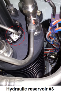
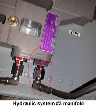
- Locate and cap the Hydraulic Reservoir Bootstrap pressure line associated with the overheating system to prevent hydraulic pressure supply to the bootstrap (see line circled in images below). Run the hydraulic system. Is the Hydraulic system still overheating?
NOTE: Cap MS21914-4K and plug MS21913-4K can be used for troubleshooting purposes.- If YES, continue with next step.
- If NO, replace the associated Hydraulic Reservoir.
- Listen around the associated system for "whooshing" fluid sound or check valve chatter. Replace suspect components and do close out.
- Replace Hydraulic System 3 Filter Elements.
- If system checks are good, do close out.
- If fault remains, continue with next step.
- Interchange the hydraulic filter manifold.
- If fault transfers over to the other side, replace defective manifold.
- If fault remains, continue with next step.
- Interchange the heat-exchanger bypass valve.
- If fault transfers over to the other side, replace defective valve.
- If fault remains, continue with next step.
- Interchange DAUs.
- If fault transfers over to the other side, replace defective DAU.
- If fault remains, continue with next step.
- Replace Hydraulic reservoir 3.
- Do close out.

