

10/04/21
Message Overview:
| DDG Reference: | 29-13-01 |
| Pilot Action (QRH): | ADVISORY 9-2 |
| System Description: | 29-13-00 |
| Schematic Diagram: | 29-13-00 [ Global Express ] [ G5000 ] [ Global XRS ] |
| Wiring Diagram: | 29-00-05 [ Global Express ] [ G5000 ] [ Global XRS ] |
Message Description:
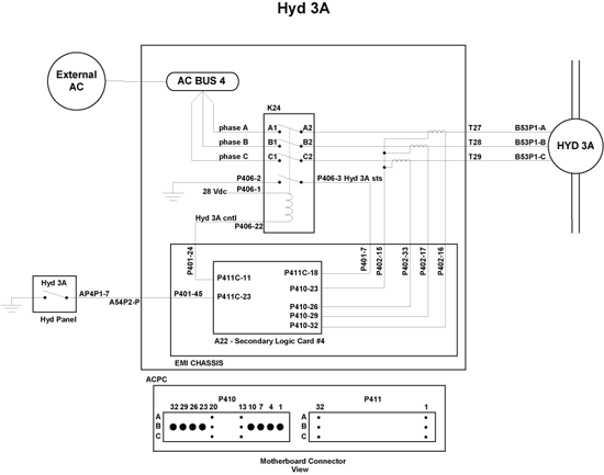
DAU 4 is receiving an input that the Hydraulic Pressure Switch 3A is less than 1800 psi (low) with Hydraulic Pump Switch 3A selected to ON.
NOTE: ACMP pressure switches close at 2400 psi (high) as pressure rises and opens at 1800 psi (low) as pressure decreases.
Possible Causes:
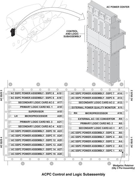
- ACPC Secondary Logic Card (SLC) 4
- AC-Motor-Driven Pump (ACMP) 3A
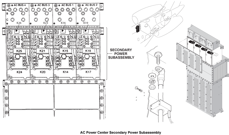
- Relay K24 in AC Power Center (ACPC)
- Hydraulic Pressure Switch 3A
- Low Hydraulic Fluid Quantity in Hydraulic System Reservoir 3
- AC Power Center (ACPC)
- Data Acquisition Unit (DAU) 4
- Associated Wiring
Troubleshooting Tips:
Advisory Wire/Service Bulletin: None
Forum Articles/Infoservice/Newsletter: None
Flight Operation Notifications Manual (FONM): None
Quick Links:
| Quantity Check of the Hydraulic Reservoir Fluid | AMM 12-12-00-610-801 [ Global Express ] [ G5000 ] [ Global XRS ] |
| Removal of Data Acquisition Units (DAU) | AMM 31-42-01-000-801 [ Global Express ] [ G5000 ] [ Global XRS ] |
| Installation of Data Acquisition Units (DAU) | AMM 31-42-01-400-801 [ Global Express ] [ G5000 ] [ Global XRS ] |
| Removal of AC Power Center (ACPC) L-Series Contactors | AMM 24-51-13-000-801 [ Global Express ] [ G5000 ] [ Global XRS ] |
| Installation of AC Power Center (ACPC) L-Series Contactors | AMM 24-51-13-400-801 [ Global Express ] [ G5000 ] [ Global XRS ] |
| Removal of ACPC | AMM 24-51-00-000-801 [ Global Express ] [ G5000 ] [ Global XRS ] |
| Installation of ACPC | AMM 24-51-00-400-801 [ Global Express ] [ G5000 ] [ Global XRS ] |
| Removal of AC Power Center (ACPC) Secondary Logic | AMM 24-51-13-000-801 [ Global Express ] [ G5000 ] [ Global XRS ] |
| Installation of AC Power Center (ACPC) Secondary Logic | AMM 24-51-13-400-801 [ Global Express ] [ G5000 ] [ Global XRS ] |
| Removal of No. 1 and No. 2 ACMP | AMM 29-12-05-000-801 [ Global Express ] [ G5000 ] [ Global XRS ] |
| Installation of No. 1 and No. 2 ACMP | AMM 29-12-05-400-801 [ Global Express ] [ G5000 ] [ Global XRS ] |
| Removal of Hydraulic Pressure Transducers | AMM 29-31-01-000-801 [ Global Express ] [ G5000 ] [ Global XRS ] |
| Installation of Hydraulic Pressure Transducers | AMM 29-31-01-400-801 [ Global Express ] [ G5000 ] [ Global XRS ] |
| Pump Operational Inhibits | FCOM 2-13-10-24 [ Global Express ] [ G5000 ] [ Global XRS ] |
| Wire Repair | SPM 20-12-10 [ Global Express ] [ G5000 ] [ Global XRS ] |
Troubleshooting Recommendations:
NOTE: Reference the Pump Operational Inhibits (Quick Links:) prior to beginning troubleshooting.
- Ensure No. 3 Hydraulic System is properly serviced.
- Operate Hydraulic Pump 3A and note Hydraulic System 3 pressure.
- If pump operates and pressure is above 2400 psi, interchange Hydraulic Pressure Switch 3A and 3B. If fault clears, do close out. If fault remains, go to step 7
- If pump operates and pressure in below 2400 psi, replace ACMP 3A and do close out.
- If pump does not operate, continue with next step.
- Perform voltage check at ACMP 3A. Check for 115 VAC at connector B53P1 between pins A and E, pins B and E and pins C and E.
- If voltage is present, replace ACMP 3A and do close out.
- If voltage is not present, continue with next step.
- Interchange ACPC SLC AC-4 with SLC AC-1.
- If system checks are good, do close out.
- If fault remains, continue with next step.
- Interchange K24 relay with K20 relay in ACPC.
- If system checks are good, do close out.
- If fault remains, continue with next step.
- Perform wiring check between ACMP 3A, ACPC Relay K24, Hydraulic Pressure Switch 3A and DAU 4.
- If fault is found / repaired, do close out.
- If fault remains, continue with next step.
- Interchange DAU 4 with DAU 2.
- If fault is no longer present. Replace failed DAU. do close out
- If fault remains, continue with next step.
- Accomplish check of EMI filter as shown below.
- Remove ACPC Secondary Logic Card 4 (SLC4)
- Measure the EMI Filter continuity from connector P410 pin 22 to aircraft structure.
- If reading is ground, replace the ACPC and do close out.
- If reading is open, continue with next step.
- Measure for open circuit between SLC 4, connector P410, pin 22 to pin 25, pin 28, and pin 31.
- If reading an open, replace the ACPC.
- Do close out

