

07/29/19
Message Overview:
| DDG Reference: | None |
| Pilot Action (QRH): | ABNORM 13-5 |
| System Description: | 32-31-00 |
| Schematic Diagram: | 32-31-00 [ Global Express ] [ G5000 ] [ Global XRS ] |
| Wiring Diagram: | 32-31-03 [ Global Express ] [ G5000 ] [ Global XRS ] |
Fault Description:
There is a landing gear not-safe condition and when a landing gear does not get to its position in 28 seconds after the landing gear control handle changes position. This message can also show incorrectly if there are one or more of the conditions that follow:
- Fault conditions show at the two inputs from one or more pairs of landing gear downlock inputs. The fault conditions relate to inputs that go to the LG ECU or are internal to the LG ECU. Inputs that go to the LG ECU (probe/sensor faults) come from the two sensors of one or more pairs of landing gear downlock sensors. Internal inputs (LG ECU internal faults) come from the pairs of signal paths and circuits that transmit the landing gear downlock inputs and calculate their condition. Fault conditions can also be a combination of a probe/sensor fault and a related LG ECU internal fault.
- A fault condition shows at one or more landing gear uplock inputs. The fault condition relates to inputs that go to the LG ECU or are internal to the LG ECU. Inputs that go to the LG ECU (probe/sensor faults) come from one or more landing gear uplock sensors. Internal inputs (LG ECU internal faults) come from the signal paths and circuits that transmit the landing gear uplock inputs and calculate their condition. Fault conditions can also be a combination of a probe/sensor fault and a related LG ECU internal fault.
- Fault conditions show at the two discrete outputs from one or more pairs of landing gear downlock outputs. The fault conditions relate to the source of the discrete outputs in the LG ECU or to the external loads that connect to the LG ECU. The source of the discrete outputs (LG ECU internal faults) is the pairs of circuits and signal paths that transmit the landing gear downlock outputs. External loads (external faults) are the LRUs that receive the landing gear downlock outputs. Fault conditions can also be a combination of an external fault and a related LG ECU internal fault.
These failures can incorrectly show a landing gear not-safe condition. They can incorrectly show that a landing gear did not get to its position in 28 seconds or less after the landing gear control handle changes position.
Possible Causes:
- A nose gear downlock proximity sensor
- One sensor of the two nose gear downlock proximity sensors is out of adjustment and the other sensor. The two nose gear downlock proximity sensors are out of adjustment. A nose gear downlock proximity sensor that is out of adjustment causes a sensor condition to not agree. See the note that follows.
- The target for one of the nose gear downlock proximity sensors is out of adjustment. The two targets for the two nose gear downlock proximity sensors are out of adjustment. A target that is out of adjustment causes a sensor condition to not agree.
- One pair, or the two pairs, of main gear downlock proximity sensors
- One sensor in a pair of main gear downlock proximity sensors is out of adjustment and the other sensor. One or two pairs of main gear downlock proximity sensors are out of adjustment. A main gear downlock proximity sensor that is out of adjustment causes a sensor condition to not agree.
- One of two targets for a pair of main gear downlock proximity sensors is out of adjustment. The targets for one pair or two pairs of main gear downlock proximity sensors are out of adjustment. A target that is out of adjustment causes a sensor condition to not agree.
- A nose gear uplock proximity sensor
- The nose gear uplock proximity sensor is out of adjustment. A nose gear uplock proximity sensor that is out of adjustment causes a sensor condition to not agree. See the note that follows.
- The target for the nose gear uplock proximity sensor is out of adjustment. A target that is out of adjustment causes a sensor condition to not agree.
- One of the two main gear uplock proximity sensors
- One of the two main gear uplock proximity sensors is out of adjustment. A main gear uplock proximity sensor that is out of adjustment causes a sensor condition to not agree.
- The target for one of the two main gear uplock proximity sensors is out of adjustment. A target that is out of adjustment causes a sensor condition to not agree
- DAU
- LGECU
- Associated Wiring
NOTE: The LGECU cannot tell what causes a sensor condition to not agree. It could be that the proximity sensor is out of adjustment or its target is out of adjustment or is defective. It could also be that the landing gear is out of adjustment or is defective. The LGECU makes a decision that the most probable cause is a proximity sensor that is out of adjustment. The LGECU sends the applicable fault message to CAIMS.
Troubleshooting Tips:
Advisory Wire/Service Bulletin: None
Forum Articles/Infoservice/Newsletter: None
Quick Links:
| Removal of LGECU | AMM 32-31-09-000-801 [ Global Express ] [ G5000 ] [ Global XRS ] |
| Installation of LGECU | AMM 32-31-09-400-801 [ Global Express ] [ G5000 ] [ Global XRS ] |
| Removal of DAUs | AMM 31-42-01-000-801 [ Global Express ] [ G5000 ] [ Global XRS ] |
| Installation of DAUs | AMM 31-42-01-400-801 [ Global Express ] [ G5000 ] [ Global XRS ] |
| Removal of Nose Gear Uplock Proximity Sensors | AMM 32-61-05-000-804 [ Global Express ] [ G5000 ] [ Global XRS ] |
| Installation of Nose Gear Uplock Proximity Sensors | AMM 32-61-05-400-804 [ Global Express ] [ G5000 ] [ Global XRS ] |
| Removal of Nose Gear Downlock Proximity Sensors | AMM 32-61-05-000-805 [ Global Express ] [ G5000 ] [ Global XRS ] |
| Installation of Nose Gear Downlock Proximity Sensors | AMM 32-61-05-400-805 [ Global Express ] [ G5000 ] [ Global XRS ] |
| Removal of Main Gear Uplock Proximity Sensors | AMM 32-61-01-000-804 [ Global Express ] [ G5000 ] [ Global XRS ] |
| Installation of Main Gear Uplock Proximity Sensors | AMM 32-61-01-400-804 [ Global Express ] [ G5000 ] [ Global XRS ] |
| Removal of Main Gear Downlock Proximity Sensors | AMM 32-61-01-000-807 [ Global Express ] [ G5000 ] [ Global XRS ] |
| Installation of Main Gear Downlock Proximity Sensors | AMM 32-61-01-400-807 [ Global Express ] [ G5000 ] [ Global XRS ] |
| Wire Repair | SPM 20-12-10 [ Global Express ] [ G5000 ] [ Global XRS ] |
Troubleshooting Recommendations:
- Select related CAIMS message below:
- If there is no available CAIMS message, continue with the steps below.
NOTE: This troubleshooting applies for one of the three following conditions: - Extension -The LGECU in CAIMS shows no faults (flight or ground) and the NVM download shows no anomalies with Channel A, or B of the LGECU. All MLG doors have opened when handle was selected down, and all three MLG did not move or come down.
- Retraction - The LGECU in CAIMS shows no faults (flight or ground) and the NVM download shows no anomalies with Channel A, or B of the LGECU. All MLG doors have opened when the gear handle was selected up, and all three MLG did move or not go up.
- NOSE STEER FAIL CAS message is posted and the Steering selector valve and/or Pressure switch 1 has been troubleshot.
- If there is no available CAIMS message, continue with the steps below.
- Ensure MLG gear down safety pins, and MLG door collars are installed, and aircraft power is “off”.
- Ensure #3 Hyd. Systems pop up indicators are all normal (not bypassed). This would indicate a valve failure due to fluid contamination. If fluid contamination is suspect, Refer to AMM 29-10-00-281-801 for acidity check.
- Re-rack the LGECU. Inspect connectors and harnesses at LGECU. Clean connectors regardless, and verify pins and sockets have appropriate drag engagement.
- Gain access to the #3 selector valve in the Main wheel well center beam. Verify that there are no hydraulic leaks.
- Disconnect connector L17P1 and inspect pins and connector for damage or FOD. Clean connectors regardless, and verify pins and sockets have appropriate drag engagement.
- With the gear handle in the down position, at connector L17P1, verify a good ground at Pin D, and open on Pin A.
- With the gear handle in the up position, at connector L17P1, verify a good ground at Pin A, and open on Pin D.
- If the conditions in steps 6 and 7 are not met, inspect wiring, MLG handle and grounds at MLG handle. Use a megger for the wiring after disconnecting the MLG Handle.
- If the conditions in steps 6 and 7 are met, continue with next step.
- Move the Gear Handle to the down position.
- Do a wiring check on the Solenoids of the valve. L17J1-Pin A to B, 57-65 ohms at 20°C (68°F). L17J1-Pin D-E, 57-65 ohms at 20°C (68°F). Check each pin to ground and ensure open. You can Freeze spray the solenoids and resistance should go down as it gets cold.
-Solenoid A (pins A-B) is gear up or retract.-Solenoid B (pins D-E) is gear down or extend.
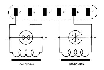
NOTE: This part is the same as #2 MLG Selector Valve and Door Selector Valve. They are all installed in the same area, so if one is suspect, do wiring checks on all the solenoids for all the valves, as they are probably all of the same age. - Using a 28 VDC power supply put 28 VDC at L17J1-between Pin A and B. Cycle on and off 10 or more times. Verify that the spool is moving in the valve. Hold the power on the solenoid for three minutes or more and verify no failures.
- Using a 28 VDC power supply put 28 VDC at L17J1-between Pin C and D. Cycle on and off 10 or more times. Verify that the spool is moving in the valve. Hold the power on the solenoid for three minutes or more and verify no failures.
- Do a wiring check between the #3 Gear Selector Valve and the LGECU. Pay attention to terminal module TM7 and verify wires and pins in this terminal module.
- If defect is found, repair defective wiring as required.
- If no defect is found, continue with next step.
- Replace LGECU.
- Do close out.