

04/03/20
Message Overview:
| DDG Reference: | 49-10-00 |
| Pilot Action (QRH): | APU 01-6 |
| System Description: | 49-60-00 |
| Schematic Diagram: | 49-61-00 [ Global Express ] [ G5000 ] [ Global XRS ] |
| Wiring Diagram: | 49-61-01 [ Global Express ] [ G5000 ] [ Global XRS ] |
Fault Description:
The aircraft is not in the correct bleed configuration when the APU LCV opening command is received.
Possible Causes:
- Data Acquisition Unit (DAU) 3 (A30)
- Data Acquisition Unit (DAU) 4 (A31)
- Bleed Management Controller (BMC) 1 (A69)
- Bleed Management Controller (BMC) 2 (A70)
- Auxiliary Power Unit (APU) Full Authority Digital Engine (Electronic) Control (FADEC) (A108)
- Left or Right Pressure Regulating Valve (PRV)
- Left or Right Wing Anti-Ice Valve (WAIV)
- Cross Bleed Valve (CBV)
- P2 (Inlet Pressure Sensor)
- Associated Wiring
Troubleshooting Tips:
Advisory Wire/Service Bulletin: None
Forum Articles/Infoservice/Newsletter:
- Customer Forum & Newsletter released on Tuesday, February 24th, 2009 / Volume 6 Issue 04
- LIEBHERR SIL LGGG436-1055-36-01
- Forum Article Bleed OFF procedure April 26, 2016
- Forum Article V- Band Clamps October 6, 2015
- Forum Article Manual Operation July 5, 2016
NOTE: You may attempt to reset the APU BLEED DISABLED advisory CAS message using the following cockpit reset procedure.
Quick Links:
| Removal of the Data Acquisition Units (DAU) | AMM 31-42-01-000-801 [ Global Express ] [ G5000 ] [ Global XRS ] |
| Installation of Data Acquisition Units (DAU) | AMM 31-42-01-400-801 [ Global Express ] [ G5000 ] [ Global XRS ] |
| Removal of the Full Authority Digital Engine Controller (FADEC) | AMM 49-61-01-000-801 [ Global Express ] [ G5000 ] [ Global XRS ] |
| Installation of the Full Authority Digital Engine Controller (FADEC) | AMM 49-61-01-400-801 [ Global Express ] [ G5000 ] [ Global XRS ] |
| Removal of Bleed Pressure Regulating and Shutoff Valve | AMM 36-11-09-000-801 [ Global Express ] [ G5000 ] [ Global XRS ] |
| Installation of Bleed Pressure Regulating and Shutoff Valve | AMM 36-11-09-400-801 [ Global Express ] [ G5000 ] [ Global XRS ] |
| Removal of Bleed Management Controller (BMC) | AMM 36-11-33-000-801 [ Global Express ] [ G5000 ] [ Global XRS ] |
| Installation of Bleed Management Controller (BMC) | AMM 36-11-33-400-801 [ Global Express ] [ G5000 ] [ Global XRS ] |
| Removal of the Anti-Icing Modulating and Shutoff Valves | AMM 30-11-01-000-801 [ Global Express ] [ G5000 ] [ Global XRS ] |
| Installation of the Anti-Icing Modulating and Shutoff Valves | AMM 30-11-01-400-801 [ Global Express ] [ G5000 ] [ Global XRS ] |
| Removal of the Inlet Pressure Sensor | AMM 49-61-13-000-801 [ Global Express ] [ G5000 ] [ Global XRS ] |
| Installation of the Inlet Pressure Sensor | AMM 49-61-13-400-801 [ Global Express ] [ G5000 ] [ Global XRS ] |
| Access to Active Faults | AMM 45-45-00-970-802 [ Global Express ] [ G5000 ] [ Global XRS ] |
| Schematic Diagram 30-11-00 | SSM 30-11-00 [ Global Express ] [ G5000 ] [ Global XRS ] |
| Schematic Diagram 36-11-00 | SSM 36-11-00 [ Global Express ] [ G5000 ] [ Global XRS ] |
| Wiring Diagram 30-11-00 | WM 30-11-00 [ Global Express ] [ G5000 ] [ Global XRS ] |
| Wiring Diagram 36-11-00 | WM 36-11-00 [ Global Express ] [ G5000 ] [ Global XRS ] |
| Wire Repair | SPM 20-12-10 [ Global Express ] [ G5000 ] [ Global XRS ] |
Troubleshooting Recommendations:
- Access CAIMS active and stored faults. Make sure there is no fault posted about the PRVs, WAIVs, CBV, APU Inlet Pressure sensor P2 or any APU related components.
- If any discrepancies are reported by the APU FADEC, left or right BMCs (CAIMS faults), follow the equivalent SmartFix Plus task.
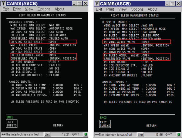
- When the condition is posted, access the Bleed synoptic page in the flight compartment. Make sure of the following:
- Left and Right PRVs show close.
- Left and Right WAIVs show close.
- CBV show close.
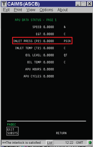
- When the condition is posted, access the Left and Right BMCs and APU FADEC CAIMS test page. Look at the discrete inputs for the PRVs, WAIVs and CBV. Make sure the PRVs, WAIVs, CBV are shown closed. Look at the P2 Inlet Pressure under the APU FADEC. Make sure there is no abnormal pressure indication or fluctuations.
- If a discrepancy is reported for any of the PRVs in the previous steps 1 to step 3, then perform the following steps:
- Swap PRVs.
- If condition follow, replace defective PRV.
- If the condition does not follow the valve then perform wiring check between PRV and BMC including the ground. Also perform wiring check between PRV and DAU3 and DAU4.
- Swap DAU3 and DAU4.
- If wiring checked OK, swap the BMCs.
- If a discrepancy is reported for any of the WAIVs in the previous steps 1 to step 3, perform the following steps:
- Swap WAIVs.
- If condition follow, replace defective WAIV.
- If the condition does not follow the valve then perform wiring check between WAIV and BMC including the ground. Also perform wiring check between the suspected WAIV and DAU3 and DAU4.
- If wiring checked OK, swap the BMCs.
- If a discrepancy is reported for the CBV in the previous steps 1 to step 3, then perform the following steps:
- Perform wiring check between CBV and BMC including the ground.
- Perform wiring check between CBV and DAU4 including the ground.
- If wiring checked OK, swap DAU3 with DAU4.
- Swap BMCs.
- If the condition does not follow BMC, replace the CBV.
- If a discrepancy is reported for the APU inlet Pressure (P2 sensor) in the previous steps 4, perform the following steps:
- Perform wiring check between APU Inlet Pressure (P2) sensor and APU FADEC.
- If wiring checked OK, replace P2 Sensor.
- If condition is still posted, replace APU FADEC.
- Do close out.

