

08/16/19
Message Overview:
| DDG Reference: | None |
| Pilot Action (QRH): | EMER 11-3 |
| System Description: | 49-60-00 |
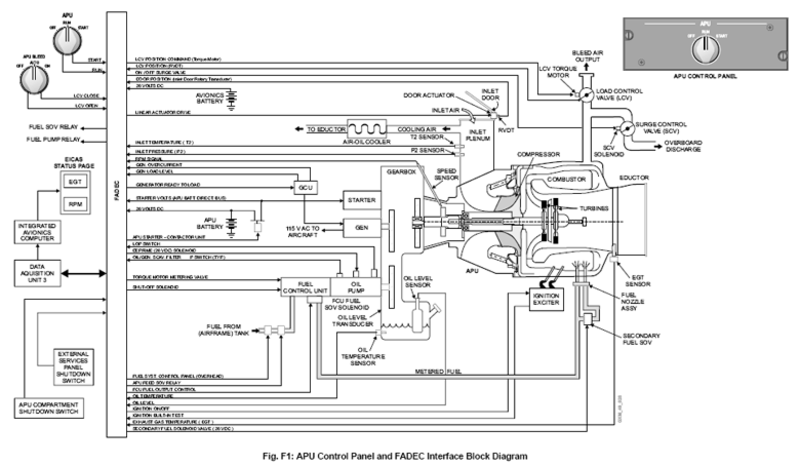
| Schematic Diagram: | 49-61-00 [ Global Express ] [ G5000 ] [ Global XRS ] |
| Wiring Diagram: | 49-61-01 [ Global Express ] [ G5000 ] [ Global XRS ] |
Fault Description:
An APU shut-down occurred, because of over speed. APU speed was greater than 106%. Automatic shut-down will occur on ground or in flight.
| Fault | See * below | Description |
|---|---|---|
| FADEC FAILURE | ECU internal failure (CPU, watchdog timer, O/S circuit failure, loss of O/S protection, etc.). | |
| O/SPD | (Hardware/Software) overspeed circuits tripped (at 106%). | |
| LOSS OF SPEED | Both monopoles failed. | |
| LOSS OF O/SPD | FADEC overspeed circuit/FCU fuel output solenoid failed. | |
| OVERTEMP | * | EGT limit exceeded during i) start ii) on-speed operation |
| FIRE EMERG | * | Fire signal is received by the FADEC. |
| REVERSE FLOW | * | T2 temp. limit (176.6°C/350°F) has been exceeded for 5 seconds. |
| HIGH OIL TEMP | * | Oil temp limit of >148.9°C exceeded for 10 seconds. |
| LOW OIL PRESS | * | Oil pressure has fallen below lower limit of 30 psig for 15 seconds, with RPM > 95%. |
| LOSS OF EGT DETECTION | * | Both EGT thermocouples have failed (NOTE: In Essential Mode, FADEC programs an EGT of 260°C to maintain the APU running). |
| NO FLAME | EGT rise has not been detected within 17 seconds of fuel solenoid being commanded open by FADEC, or RPM >18% for 5 seconds. | |
| NO ACCEL | Acceleration is < 0.05% of the prescheduled rate (normal acceleration is 2.5% per second). | |
| SLOW SPEED | Starter timer expired - APU RPM > 5% and less than starter cut-out for 30 seconds. | |
| UNDER SPEED | * | Speed has reached 100%, then drops below 80% for 5 seconds. |
| NO CRANK | RPM does not rise above 5% within: a) 2 secs. when oil temp is warmer than minus 23°C, or b) 50 secs. when oil temp is minus 23°C or lower. |
|
| INLET DOOR | Inlet door position indicates closed 30 secs before starter engagement, or 600 msecs. after starter engagement. | |
| LOSS OF DC POWER | Loss of 28 VDC power for 200 milliseconds. | |
| LOP SW FAIL | * | Oil pressure switch has failed open when RPM is < 7%. NOTE: This switch is normally closed during prestart BITE. |
| FALLBACK | APU drop below 25% RPM after starter cut-out | |
| APU GCU HIGH OIL TEMP | * | APU Generator oil temperature above 215°C |
| NOTE: An asterisk mark (*) in any row above means that the automatic protection shut-down on that row is inhibited if the associated fault occurs in flight. The respective CAS message, or an advisory message reading APU FAULT will be displayed in the CAS window and the APU will not shut down automatically in flight. However the pilot may select to shut-down the APU manually by placing the APU control switch to "OFF". | ||
Possible Causes:
- Auxiliary Power Unit (APU) Full-Authority Digital Engine-Controller (FADEC)
- Engine Branched Wiring Harness
- Aircraft Wiring Harness
- Fuel Control Unit (FCU)
Troubleshooting Tips:
Advisory Wire/Service Bulletin: None
Forum Articles/Infoservice/Newsletter: None
NOTE: Make sure the APU OVERSPEED or OVERTEMP is not the result of De-Ice / Anti-Ice fluid ingestion while the APU was in operation.
WARNING: DE-ICE/ANTI-ICE FLUIDS ARE FLAMMABLE AND VERY CORROSIVE. INGESTION OF THESE FLUIDS IN AN OPERATING APU MAY CAUSE APU DAMAGE AND INJURY TO PERSONNEL SERVICING THE AIRCRAFT
Quick Links:
| Access to Active Faults | AMM 45-45-00-970-802 [ Global Express ] [ G5000 ] [ Global XRS ] |
| Access to Stored Faults | AMM 45-45-00-970-803 [ Global Express ] [ G5000 ] [ Global XRS ] |
| Access to System Diagnostics | AMM 45-45-00-970-804 [ Global Express ] [ G5000 ] [ Global XRS ] |
| Removal of the Fuel Control Unit | AMM 49-30-01-000-801 [ Global Express ] [ G5000 ] [ Global XRS ] |
| Installation of the Fuel Control Unit | AMM 49-30-01-400-801 [ Global Express ] [ G5000 ] [ Global XRS ] |
| Removal of the Engine Branched Wiring Harness | AMM 49-12-01-000-801 [ Global Express ] [ G5000 ] [ Global XRS ] |
| Installation of the Engine Branched Wiring Harness | AMM 49-12-01-400-801 [ Global Express ] [ G5000 ] [ Global XRS ] |
| Removal of the Full-Authority Digital Engine-Controller (FADEC) | AMM 49-61-01-000-801 [ Global Express ] [ G5000 ] [ Global XRS ] |
| Installation of the Full-Authority Digital Engine-Controller (FADEC) | AMM 49-61-01-400-801 [ Global Express ] [ G5000 ] [ Global XRS ] |
| APU Electrical Harness Wiring Diagram 49-12-00 | WM 49-12-00 [ Global Express ] |
Troubleshooting Recommendations:
- Remove APU FADEC and do a visual inspection of the FADEC rack, pins and sockets for damage or FOD.
- Disconnect the MPE1P1 connector from the LCV, and inspect for contamination and damage. Re-connect if nothing found.
- Disconnect the A3P1 connector from the FCU (A3) and inspect for contamination and damage. Re-connect if nothing found.
- Disconnect the MT4P1 connector from the APU Speed Sensor (MT4) and inspect for contamination and damage. Re-connect if nothing found.
- Check for 33Ω to 41Ω on APU FADEC connector A108AP1 pins F2 and G2. Check each pin (F2/ G2) individually to ground and ensure circuit is open. This is the FCU torque motor circuit.
- Check for 18Ω to 33Ω on APU FADEC connector A108BP1 between pins A1 and B1. Check each pin (A1/ B1) individually to ground and ensure circuit is open This is the FCU shut-off solenoid.
- Check at APU FADEC connector A108AP1, between pins G11, and H11, value to be ≈24.9Ω. Check between pins J11 and K11, value to be ≈33.9Ω. Check each of the above four pins to ground and ensure no continuity. This is the speed sensor (dual channel).
- Re-Rack APU FADEC
- If system checks are good, do the close out.
- If fault remains continue with next step.
- Access CAIMS/ System Diagnostics/ ATA 49/ FADEC/ LRU TEST/ APU DATA STATUS page 1, and read EGT DATA. Back out and go to APU DATA STATUS page 2, and read EGT data. Compare the two and ensure they are the same or close to the same value. (Page 1 is channel 1, Page 2 is channel 2). Compare the rest of the data on these two pages to current conditions and ensure it is accurate. If possible read this data with, and without the APU running to have as much data as possible. If you suspect a sensor; remember what you are reading is real time (give or take 5 seconds), so have an assistant change the sensor physically (temp./pressure) and verify the changes in CAIMS.
- Replace Speed Sensor, or swap with a known good sensor for troubleshooting.
- If system checks are good, do close out.
- If fault remains, continue with next step.
- Replace the APU FADEC, or swap with a known good APU FADEC for troubleshooting.
- Do close out.