

02/08/21
Message Overview:
Message Name:
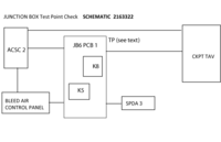
[ACSC2-A] CKPT TRIM AIR VLV CMD/TAV
Message Code:
2163322ECS
Associated CAS:
| Reporting LRU: | Air Conditioning System Controller (ACSC) 2 |
| System Description: | 21-60-00 |
| Schematic Diagram: | 21-60-00 [ Global Express ] [ G5000 ] [ Global XRS ] |
| Wiring Diagram: | 21-60-01 [ Global Express ] [ G5000 ] [ Global XRS ] |
Message Description:
The CKPT TAV (L26) position does not agree with the Air Conditioning System Controller (ACSC) 2 Ch. A command. Inhibited during Take-off and Landing.
Possible Causes:
- Cockpit Trim Air Valve (CKPT TAV) (L26)
- Secondary-Power Distribution Assembly (SPDA) 3 (A15)
- Air Conditioning System Controller (ACSC) 2 (A88)
- Bleed Air Control Panel (TRIM AIR Switch/ circuit /wiring) (AP8)
- Junction Box (JB6)
- Associated Wiring
Troubleshooting Tips:
Advisory Wire/Service Bulletin: None
Forum Articles/Infoservice/Newsletter: None
NOTE: Before removing JB6, replace PCB1 Circuit Card if available.
NOTE: Use spare Relay if necessary.
Quick Links:
| Removal of the Trim Air Valves | AMM 21-60-13-000-801 [ Global Express ] [ G5000 ] [ Global XRS ] |
| Installation of the Trim Air Valves | AMM 21-60-13-400-801 [ Global Express ] [ G5000 ] [ Global XRS ] |
| Removal of the Air-Conditioning System Controllers | AMM 21-60-21-000-801 [ Global Express ] [ G5000 ] [ Global XRS ] |
| Installation of the Air-Conditioning System Controllers | AMM 21-60-21-400-801 [ Global Express ] [ G5000 ] [ Global XRS ] |
| Removal of the Junction Box JB6 | AMM 24-00-13-000-801 [ Global Express ] [ G5000 ] [ Global XRS ] |
| Installation of the Junction Box JB6 | AMM 24-00-13-400-801 [ Global Express ] [ G5000 ] [ Global XRS ] |
| Removal of the Secondary-Power Distribution Assemblies | AMM 24-62-01-000-801 [ Global Express ] [ G5000 ] [ Global XRS ] |
| Installation of the Secondary-Power Distribution Assemblies | AMM 24-62-01-400-801 [ Global Express ] [ G5000 ] [ Global XRS ] |
| Wire Repair - Maintenance Practices - ALL | SPM 20-12-10-02 [ Global Express ] [ G5000 ] [ Global XRS ] |
Troubleshooting Recommendations:
- Interchange Trim Air Valves (TAV). Is the fault still present?
- If YES, continue with next step.
- If NO, replace defective TAV.
- Interchange SPDA 2 with SPDA 3.Is the fault still present?
- If YES, continue with next step.
- If NO, replace defective SPDA.
- Interchange ACSCs. Is the fault still present?
- If YES, continue with next step.
- If NO, replace defective ACSC
- Perform wiring checks via TP-45, TP-42, TP-48, TP-16, TP-17, TP-49, TP-18, between ACSC 2, Relay K8/PCB1/JB5, Relay K5/PCB1/JB5, JB6, the Trim Air Control Panel and the CKPT TAV.
- If wiring defects are found, repair defective wiring as required and do close out.
- If defects are found, continue with next step.
- Perform wiring checks between ACSC 2, the Trim Air Control Panel and the CKPT TAV.
- If wiring defects are found, repair defective wiring as required and do close out.
- If defects are found, continue with next step.
- Check the Trim Air Control Panel functionality.
- If defects are found, replace/repair as required.
- If no defects are found, continue with next step.
- Replace JB6.
- Do close out.
