03/04/20
Message Overview:
Fault Message:
GCU2 SENSE/GEN2 CONT SW FAULT
Fault Code:
2422254LPS
Associated CAS:
| Reporting LRU: | Generator Control Unit (GCU) 2 |
| System Description: | 24-21-00 |
| Schematic Diagram: | 24-21-00 [ Global Express ] [ G5000 ] [ Global XRS ] |
| Wiring Diagram: | 24-21-02 [ Global Express ] [ G5000 ] [ Global XRS ] |
Fault Description:
Generator Control Unit (GCU) 2 has detected a fault in the Generator Control Switch (GCS)/wiring or in its internal GCS sensing circuit.
GCU GCS sensing circuit has detected the OFF signal as being the same as the ON signal.
Possible Causes:
- Generator Control Unit (GCU) 2 (A57)
- Generator Control Switch (GCS)
- Associated Wiring
Troubleshooting Tips:
Advisory Wire/Service Bulletin: None
Forum Articles/Infoservice/Newsletter: None
A GCU patch cable (GSE REF # 24X-24-02) can be used to swap GCUs 1, 4 and 5 into position 2 or 3 (for troubleshooting only).
The GCU NVMs can only be downloaded at position #2 or #3.
Quick Links:
| Removal of the Generator Control Units (GCU) | AMM 24-24-01-000-801 [ Global Express ] [ G5000 ] [ Global XRS ] |
| Installation of the Generator Control Units (GCU) | AMM 24-24-01-400-801 [ Global Express ] [ G5000 ] [ Global XRS ] |
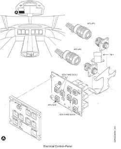
| Removal of the ELECTRICAL Control Panel | AMM 24-24-05-000-801 [ Global Express ] [ G5000 ] [ Global XRS ] |
| Installation of the ELECTRICAL Control Panel | AMM 24-24-05-400-801 [ Global Express ] [ G5000 ] [ Global XRS ] |
| Wire Repair - Maintenance Practices - ALL | SPM 20-12-10-02 [ Global Express ] [ G5000 ] [ Global XRS ] |
Troubleshooting Recommendations:
- Swap GCU 2 with GCU 3.
- If system checks are good, replace the GCU 2 and do close out.
- If fault remains, continue with next step.
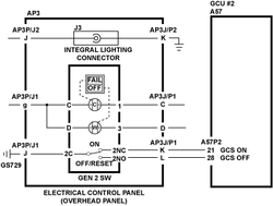
- Disconnect both GCU 2 connector A57P2 and overhead control panel connector AP3P1. Perform a wiring check (open circuits check) between interface wiring GCU/Electrical Control Panel as follows:
From To Result A57P2-21 AP3P1-K A57P2-28 AP3P1-L - If wiring checks are not good, repair wiring as required and do close out.
- If wiring checks are good, continue with next step.
- Perform a wiring check (short circuits check) between interface wiring GCU/Electrical Control Panel as follow:
From To Result A57P2-21 Ground A57P2-28 Ground - If wiring checks are not good, repair wiring as required and do close out.
- If wiring checks are good, continue with next step.
- Perform a continuity check between the Electrical Control Panel and ground as follows:
From To Result AP3P1-J Ground - If there is continuity, repair wiring as required and do close out.
- If there is no continuity, continue with next step.
- Perform a continuity check between the Electrical Control Panel and ground stud as follows:
From To Result AP3P1-J GS729 - If there is continuity, check the integrity of ground stud GS729 and repair wiring as required and do close out.
- If there is no continuity, continue with next step.
- Inspect the electrical control panel internal wiring and the generator control switch (GCS-SDS4).
- If wiring checks are not good, repair wiring as required and do close out.
- If wiring checks are good, continue with next step.
- Replace GCS.
- Do close out.