05/15/24
Message Overview:
Fault Message:
ASCA FAILED-ACPC (LEVEL C)
Fault Code:
2451384ACP
| Reporting LRU: | Auxiliary Power Unit (APU) |
| Associated CAS: | ELEC SYS FAULT (Advisory) |
| System Description: | 24-60-00 - DC Electrical Load Distribution |
| Schematic Diagram: | [ Global Express ] [ G5000 ] [ Global XRS ] 24-32-00 - Battery System [ Global Express ] [ G5000 ] [ Global XRS ] 24-62-05-101 - DC Load Distribution APU Starter Contactor Assembly (ASCA) System -Electrical Schematic |
| Wiring Diagram: | [ Global Express ] [ G5000 ] [ Global XRS ] 24-62-05-01 - APU Battery Power Control System [ Post SB700-24-034 And 9003, 9004, 9025, 9052-9069, 9070-9084 ] [ Global Express ] [ G5000 ] [ Global XRS ] 24-62-05-02 - APU Battery Power Control System [ 9085-9158 ] [ Global Express ] [ G5000 ] [ Global XRS ] 24-62-15-1 - APU Battery Power Control [ 9127-9129 ] [ Global Express ] [ G5000 ] [ Global XRS ] 24-62-15-1 - APU Battery Power Control [ All ] [ Global Express ] [ G5000 ] [ Global XRS ] 24-62-15-2 - APU Battery Power Control [ 9130-9249 ] [ Global Express ] [ G5000 ] [ Global XRS ] 24-62-15-3 - APU Battery Power Control [ 9250-9431, 9998 ] |
Message Description:
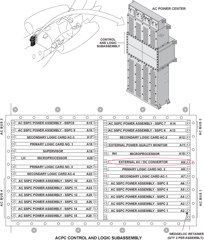
The AC-to-DC Converter Card in the AC Power Center (ACPC) detects a discrepancy between the fuses output voltage status on the output terminal and the related power input voltage of the Auxiliary Power Unit (APU) Starter-Contactor Assembly (ASCA) External DC Power Quality Monitor (EDPQM).
Possible Causes:
- AC Power Center (ACPC) AC-to-DC Converter Card
- AC Power Center (ACPC) (A54)
- Auxiliary Power Unit (APU) Starter-Contactor Assembly (ASCA) (A48)
- Associated Wiring
Troubleshooting Tips:
Advisory Wire/Service Bulletin: None
Forum Articles/Infoservice/Newsletter: None
Quick Links:
| Removal of the AC Power Center (ACPC) | AMM 24-51-00-000-801 [ Global Express ] [ G5000 ] [ Global XRS ] |
| Installation of the AC Power Center (ACPC) | AMM 24-51-00-400-801 [ Global Express ] [ G5000 ] [ Global XRS ] |
| Removal of the AC Power Center (ACPC) External AC-to-DC Converter |
AMM 24-51-17-000-801 [ Global Express ] [ G5000 ] [ Global XRS ] |
| Installation of the AC Power Center (ACPC) External AC-to-DC Converter |
AMM 24-51-17-400-801 [ Global Express ] [ G5000 ] [ Global XRS ] |
| Removal of the APU Starter-Contactor Assembly | AMM 24-62-05-000-801 [ Global Express ] [ G5000 ] [ Global XRS ] |
| Installation of the APU Starter-Contactor Assembly | AMM 24-62-05-400-801 [ Global Express ] [ G5000 ] [ Global XRS ] |
| Operational Test of the APU Starter−Contactor Assembly | AMM 24−62−05−710−801 [ Global Express ] [ G5000 ] [ Global XRS ] |
| Wire Repair - Maintenance Practices - ALL | SPM 20-12-10-02 [ Global Express ] [ G5000 ] [ Global XRS ] |
Troubleshooting Recommendations:
- Get access to the Auxiliary Power Unit (APU) Battery and disconnect connector A89P2.
- Get access to the APU Start Contactor Assembly (ASCA) and disconnect connector A48P2.
- Remove Alternating Control Power Center (ACPC) A/D converter card.
- Do wiring checks between the following connections:
From To Result A48P2-K P520A-5 A48P2-R P520A-35 ASCA To ACPC Schematic 
- If there is no continuity, repair defective wiring as required and do close out.
- If there is continuity, continue with the next step.
- Do continuity checks between the following connections:
From To Result A48P2-K Ground A48P2-R Ground - If there is continuity, continue with the next step
- If there is no continuity, go to step 8
- Get access to the ACPC and disconnect connector A54P4.
- Do continuity checks between ASCA and ground as follow:
From To Result A48P2-K Ground A48P2-R Ground - If there is continuity, repair defective wiring as required and do close out.
- If there is continuity, go to step 11
- Get access to "view fault messages" in the OMS and check for ACPC external A/D converter card (A9) failed message.
- If there is no fault message, go to step 10.
- If there is fault message, continue with the next step.
- Replace A/D converter card.
- If system checks are good, do close out.
- If fault remains, continue with the next step.
- Replace ASCA.
- If system checks are good, do close out.
- If fault remains, continue with the next step.
- Replace ACPC
- Do close out.