01/11/22
Message Overview:
Message Name:
TRU 1 FAN FAILED
Message Code:
2460460DCP
Associated CAS:
| Reporting LRU: | DC Power Center (DCPC) |
| System Description: | 24-31-00 |
| Schematic Diagram: | [ Global Express ] [ G5000 ] [ Global XRS ] 24-31-00 DC Power Conversion System [ Global Express ] [ G5000 ] [ Global XRS ] 24-51-00 AC Load Distribution AC Power Center (ACPC) System [ Global Express ] [ G5000 ] [ Global XRS ] 24-52-00 AC Load Distribution Cockpit Circuit Breaker Panel (CCBP) System. |
| Wiring Diagram: | [ Global Express ] [ G5000 ] [ Global XRS ] 24-31-01 Transformer Rectifiers [ Global Express ] [ G5000 ] [ Global XRS ] 24-51-00 ACPC Distribution Left [ Global Express ] [ G5000 ] [ Global XRS ] 24-51-00 ACPC Distribution Right [ Global Express ] [ G5000 ] [ Global XRS ] 24-52-01 Cockpit Circuit Breaker Panel (CCBP) |
Message Description:
The Transformer Rectifier Unit (TRU) 1 Fan Speed Sensor is low or no Fan output to the DC Power Center (DCPC).
Possible Causes:
- DC Power Center (DCPC) (A63)
- DC Power Quality Monitor (DCPQM) Card 1
- Transformer Rectifier Unit (TRU) 1 (A73)
- Associated Wiring
Troubleshooting Tips:
Advisory Wire/Service Bulletin: None
Forum Articles/Infoservice/Newsletter: None
NOTE: The TRU 1 fan fail will show on the DC synoptic page, as the TRU 1 outline will be amber and the TRU output voltage is approximately 28 VDC.
NOTE: If the TRU voltage displayed on the DC synoptic page is different than 28 VDC, check that all three 115 VAC input phases are present. A missing phase could result in the fan not spinning.
NOTE: Verify C/B status on both pilot and copilot EMS CDUs. This Fault Message will post if either of the following circuit breaker or Smart Contactor status is OUT or Tripped.
| LOCATION | CB NO. | NAME |
|---|---|---|
| CCBP (A54) | CB-G12 | TRU BAY FAN |
| ACPC (A35) | SC-K15 | AC 1 FEED |
Quick Links:
| Removal of the Transformer Rectifier Units | AMM 24-31-01-000-801 [ Global Express ] [ G5000 ] [ Global XRS ] |
| Installation of the Transformer Rectifier Units | AMM 24-31-01-400-801 [ Global Express ] [ G5000 ] [ Global XRS ] |
| Removal of the DC Power Center (DCPC) | AMM 24-61-00-000-801 [ Global Express ] [ G5000 ] [ Global XRS ] |
| Installation of the DC Power Center (DCPC) | AMM 24-61-00-400-801 [ Global Express ] [ G5000 ] [ Global XRS ] |
| Removal of the DC Power Center (DCPC) DC Power Quality Monitor | AMM 24-61-13-000-801 [ Global Express ] [ G5000 ] [ Global XRS ] |
| Installation of the DC Power Center (DCPC) DC Power Quality Monitor | AMM 24-61-13-400-801 [ Global Express ] [ G5000 ] [ Global XRS ] |
| Access to Active Faults | AMM 45-45-00-970-802 [ Global Express ] [ G5000 ] [ Global XRS ] |
| Access to Stored Faults | AMM 45-45-00-970-803 [ Global Express ] [ G5000 ] [ Global XRS ] |
| Wire Repair - Maintenance Practices - ALL | SPM 20-12-10-02 [ Global Express ] [ G5000 ] [ Global XRS ] |
Troubleshooting Recommendations:
- Check status of AC 1 FEED on EMS CDU, the AC 1 Feed being out or tripped can drive multiple CAS to post.
BUS > AC 1 > AC 1 FEED.- If AC 1 FEED CB is IN go to step 3.
- If AC 1 FEED CB is OUT, set to IN.
AC 1 FEED CB SYSTEM PHASE CAS CB-G6 ESS TRU 1 3 AC BUS 1 FAIL (Caution) CB-G3 EVS FAIRING HEAT 3 EVS HEAT FAIL (Caution) CB-G9 SLAT/FLAP PWR 1 3 SLAT-FLAP HALFSPD (Advisory) CB-H5 EVS WINDOW HEAT 1 EVS HEAT FAIL (Caution) CB-H6 A/T CTLR 1 A/T 1 FAIL (Advisory)
A/T 2 FAIL (Advisory)CB-H7 PITOT 1 HT A 1 PITOT 1 HT FAIL (Caution) CB-H8 R ICE DETECTOR 1 ICE DETECTOR FAULT (Advisory) CB-H9 R AOA HEAT A 1 R AOA HEAT FAIL (Caution) CB-H10 L WSHLD HEAT 1 1 L WSHLD HEAT FAIL (Caution) CB-H11 L WSHLD HEAT 2 1 L WSHLD HEAT FAIL (Caution) CB-G12 TRU BAY FAN 3 ELEC SYS FAULT (Advisory)
2460460DCP TRU 1 FAN FAILEDCB-B6 STAB TRIM CH1 3 STAB CH 1 FAIL (Advisory)
- Did the CAIMS Fault & CAS messages clear after setting AC 1 FEED CB to IN.
- If YES, do close out.
- If NO, go to next step.
- Get Access to the FWD bay to check for the airflow of the TRU 1 and confirm if the fan is rotating or not.
- If the fan is not rotating, replace TRU 1 and do close out.
- If the fan is rotating, continue with next step.
- Interchange TRU 1 with another TRU. Is the fault still present?
- If YES, continue with next step.
- If NO, replace defective TRU.
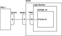
- Disconnect TRU 1 connector A73P1 and DCPC connector A63P1. Perform a continuity check as follows:
From To Result A73P1-D Ground - If there is continuity, repair defective wiring as required and do close out.
- If there is no continuity, continue with next step.
- Perform a continuity check as follows:
From To Result A73P1-D A63P1-A - If there is no continuity, repair defective wiring as required and do close out.
- If there is continuity, continue with next step.
- Access the DCPC Logic assembly and remove the DCPQM 1 card. Perform a continuity check as follows:
From To Result A63P1-A Ground - If there is continuity, go to step 8.
- If there is no continuity, continue with next step.
- Perform a continuity check as follows:
From To Result A63P1-A P121A-10 - If there is no continuity, go to step 8.
- If there is continuity, continue with next step.
- Replace the DCPQM 1 card.
- If system checks are good, do close out.
- If fault remains, continue with next step.
- Replace DCPC.
- Do close out.