10/05/20
Message Overview:
Fault Message:
TRU 1 FAILED/TRU 1 FEEDER/WRG FAIL
Fault Code:
2460461DCP
Associated CAS:
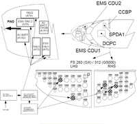
| Reporting LRU: | DC Power Center (DCPC) |
| System Description: | 24-60-00 |
| Schematic Diagram: | 24-31-00 [ Global Express ] [ G5000 ] [ Global XRS ] |
| Wiring Diagram: | 24-31-01 [ Global Express ] [ G5000 ] [ Global XRS ] |
Fault Description:
DC Power Center (DCPC) has detected a Transformer Rectifier Unit (TRU) 1 failure.
Possible Causes:
- Transformer Rectifier Unit (TRU) 1 (A73)
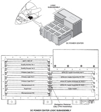
- DC Power Center (DCPC) (A63)
- DC Power Quality Monitor (DCPQM) Card 1
- DC Power Center (DCPC) Electronic Module 1
- DC Power Center (DCPC) Primary Logic Card
- Associated Wiring
Troubleshooting Tips:
Advisory Wire/Service Bulletin: None
Forum Articles/Infoservice/Newsletter: None
If the TRU voltage indication on the DC synoptic page is less than 26 volts, suspect a bad or a missing input phase from the AC system (ACPC).
Quick Links:
| Removal of the Transformer Rectifier Units | AMM 24-31-01-000-801 [ Global Express ] [ G5000 ] [ Global XRS ] |
| Installation of the Transformer Rectifier Units | AMM 24-31-01-400-801 [ Global Express ] [ G5000 ] [ Global XRS ] |
| Removal of the DC Power Center (DCPC) | AMM 24-61-00-000-801 [ Global Express ] [ G5000 ] [ Global XRS ] |
| Installation of the DC Power Center (DCPC) | AMM 24-61-00-400-801 [ Global Express ] [ G5000 ] [ Global XRS ] |
| Removal of the DC Power Center (DCPC) DC Power Quality Monitor | AMM 24-61-13-000-801 [ Global Express ] [ G5000 ] [ Global XRS ] |
| Installation of the DC Power Center (DCPC) DC Power Quality Monitor | AMM 24-61-13-400-801 [ Global Express ] [ G5000 ] [ Global XRS ] |
| Removal of the DC Power Center (DCPC) Electronic Modules | AMM 24-61-65-000-801 [ Global Express ] [ G5000 ] [ Global XRS ] |
| Installation of the DC Power Center (DCPC) Electronic Modules | AMM 24-61-65-400-801 [ Global Express ] [ G5000 ] [ Global XRS ] |
| Wire Repair - Maintenance Practices - ALL | SPM 20-12-10-02 [ Global Express ] [ G5000 ] [ Global XRS ] |
Troubleshooting Recommendations:
- Swap the TRU 1 with ESS TRU 1.
- If system checks are good, replace TRU 1 and do close out.
- If fault remains, continue with next step.
- Check for 115 VAC of TRU voltage input phases.
- If voltage are good, go to step 4.
- If one or more of the phases are less than 115 VAC, continue with next step.
- Troubleshoot the power input from the ACPC (AC BUS 2). Repair as required.
- If system checks are good, do close out.
- If fault remains, continue with next step.
- Check for 24 VDC at the DCPC input (stud T1) with load on the system.
NOTE: Use an oscilloscope to take the measurement in order to make sure there is no fluctuation of the DC signal.- If voltage are good, go to step 6.
- If one or more of the phases are less than 22 VDC, continue with next step.
- Perform wiring checks between DCPC and the TRU 1.
- If wiring checks are not good, repair defective wiring as required and do close out.
- If wiring checks are good, continue with next step.
- Swap DCPQM card 1 and the DCPQM card 2 in DCPC.
- If system checks are good, replace DCPQM card 1 in DCPC and do close out.
- If fault remains, continue with next step.
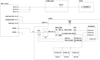
- In the DCPC, remove the three Primary Logic Cards, the DCPQM card 1 and disconnect connector P105 of Electronic Module 1.
- Perform an EMI filter check by performing a continuity check as follows:
From To Result P105-8 Ground P105-10 Ground - If there is continuity, go to step 11.
- If there is no continuity, continue with next step.
- Check the resistances of the Electronic Module 1 as follows:
From To Expected Result Result J105-8 J105-9 2 kΩ J105-9 J105-10 1.5 kΩ - If resistance is within range, go to step 11.
- If resistance is out of range, continue with next step.
- Replace EM1.
- If system checks are good, do close out.
- If fault remains, continue with next step.
- Replace DCPC.
- Do close out.