06/28/19
Message Overview:
Fault Message:
FUSE F2-ELECTRONIC MODULE #1 FAILED
Fault Code:
2460496DCP
Associated CAS:
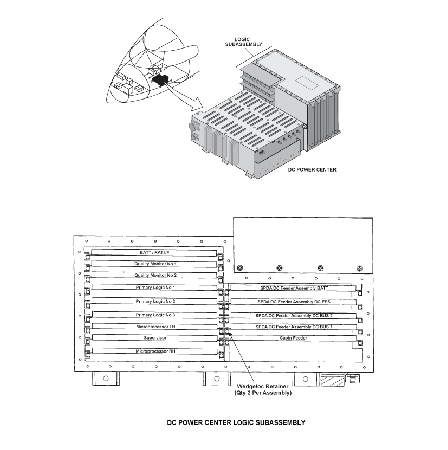
| Reporting LRU: | DC Power Center (DCPC) |
| System Description: | 24-60-00 |
| Schematic Diagram: | 24-61-00 [ Global Express ] [ G5000 ] [ Global XRS ] |
| Wiring Diagram: | 24-61-01 [ Global Express ] [ G5000 ] [ Global XRS ] |
Fault Description:
DC Power Center (DCPC) has detected a defective Electrical Module 1 (EM1) Fuse F2.
Possible Causes:
- Electronic Module 1 (EM1)
- DC Power Center (DCPC) Right Microprocessor Card
- DC Power Center (DCPC) Battery/Ram-Air-Turbine Interface Unit
- DC 1 Feeder Card
- DC Power Center (DCPC) (A63)
- Associated Wiring
Troubleshooting Tips:
Advisory Wire/Service Bulletin: None
Forum Articles/Infoservice/Newsletter: None
Quick Links:
| Removal of the DC Power Center (DCPC) | AMM 24-61-00-000-801 [ Global Express ] [ G5000 ] [ Global XRS ] |
| Installation of the DC Power Center (DCPC) | AMM 24-61-00-400-801 [ Global Express ] [ G5000 ] [ Global XRS ] |
| Removal of the DC Power Center (DCPC) Fault-Tolerant Microprocessor | AMM 24-61-05-000-801 [ Global Express ] [ G5000 ] [ Global XRS ] |
| Installation of the DC Power Center (DCPC) Fault-Tolerant Microprocessor | AMM 24-61-05-400-801 [ Global Express ] [ G5000 ] [ Global XRS ] |
| Removal of the DC Power Center (DCPC) Battery/ Ram-Air-Turbine Interface Unit | AMM 24-61-33-000-801 [ Global Express ] [ G5000 ] [ Global XRS ] |
| Installation of the DC Power Center (DCPC) Battery/ Ram-Air-Turbine Interface Unit | AMM 24-61-33-400-801 [ Global Express ] [ G5000 ] [ Global XRS ] |
| Removal of the DC Power Center (DCPC) Secondary-Power Distribution Assembly (SPDA) Feeder | AMM 24-61-37-000-801 [ Global Express ] [ G5000 ] [ Global XRS ] |
| Installation of the DC Power Center (DCPC) Secondary-Power Distribution Assembly (SPDA) Feeder | AMM 24-61-37-400-801 [ Global Express ] [ G5000 ] [ Global XRS ] |
| Removal of the DC Power Center (DCPC) Electronic Modules | AMM 24-61-65-000-801 [ Global Express ] [ G5000 ] [ Global XRS ] |
| Installation of the DC Power Center (DCPC) Electronic Modules | AMM 24-61-65-400-801 [ Global Express ] [ G5000 ] [ Global XRS ] |
| Wire Repair - Maintenance Practices - ALL | SPM 20-12-10-02 [ Global Express ] [ G5000 ] [ Global XRS ] |
Troubleshooting Recommendations:
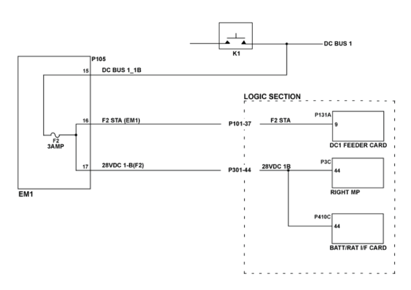
- Remove the DC 1 Feeder Card, Battery/RAT I/F Card and the Right Microprocessor from the DCPC.
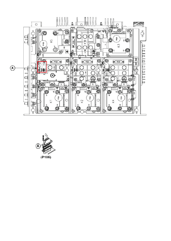
- Disconnect connector P105 of EM 1.
- Perform a continuity check as follows:
From To Result J105-15 J105-16 - If there is continuity, continue with next step.
- If there is no continuity, go to step 9.
- Perform a continuity check as follows:
From To Result P105-16 Ground P105-17 Ground - If there is continuity, go to step 10.
- If there is no continuity, continue with next step.
- Perform a continuity check as follows:
From To Result P105-16 P131A-9 P105-17 P3C-44 P105-17 P410C-44 - If there is continuity, continue with next step.
- If there is no continuity, go to step 10.
- Swap the DC 1 feeder card with the DC 2 feeder card. Does the fault transfer over to EM 2?
- If YES, replace DC 1 feeder card and do close out.
- If NO, continue with next step.
- Swap the Right Microprocessor with the Left Microprocessor. Is the fault resolved?
- If YES, replace Right Microprocessor and do close out.
- If NO, continue with next step.
- Replace BATT/RAT I/F card. Is the fault resolved?
- If YES, do close out.
- If NO, continue with next step.
- Replace EM 1.
- If system checks are good, do close out.
- If fault remains, continue with next step.
- Replace DCPC.
- Do close out.