07/01/19
Message Overview:
Fault Message:
SPDA 2 FAILED (LEVEL C)-LEFT FUSE#2
Fault Code:
2463209SPD
Associated CAS:
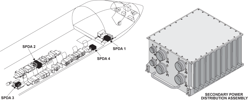
| Reporting LRU: | Secondary Power Distribution Assembly (SPDA) 2 |
| System Description: | 24-60-00 |
| Schematic Diagram: | 24-61-00 [ Global Express ] [ G5000 ] [ Global XRS ] |
| Wiring Diagram: | 24-61-01 [ Global Express ] [ G5000 ] [ Global XRS ] 24-62-02 [ Global Express ] [ G5000 ] [ Global XRS ] 24-62-05 [ Global Express ] [ G5000 ] [ Global XRS ] |
Fault Description:
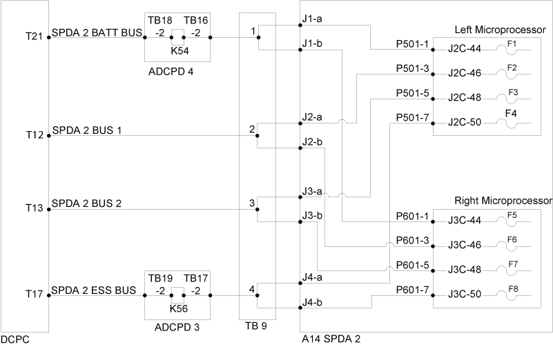
Fuse F2 on Left Microprocessor in Secondary Power Distribution Assembly (SPDA) 2 is blown as reported by the SPDA 2.
NOTE: Clear all short circuits prior to swapping or replacing LRUs.
Possible Causes:
- Secondary Power Distribution Assembly (SPDA) 2 (A14)
- Secondary Power Distribution Assembly (SPDA) DC Feeder Assembly DC BUS 1
- DC Power Center (DCPC) (A63)
- Associated Wiring
Troubleshooting Tips:
Advisory Wire/Service Bulletin:
- AW700-24-0252 - “ELEC SYS FAULT” and or “ELEC SYS FAIL” - Nuisance CAS Message during Power Up
Forum Articles/Infoservice/Newsletter: None
Quick Links:
| Removal of the DC Power Center (DCPC) | AMM 24-61-00-000-801 [ Global Express ] [ G5000 ] [ Global XRS ] |
| Installation of the DC Power Center (DCPC) | AMM 24-61-00-400-801 [ Global Express ] [ G5000 ] [ Global XRS ] |
| Removal of the DC Power Center (DCPC)Secondary-Power Distribution Assembly (SPDA) Feeder | AMM 24-61-37-000-801 [ Global Express ] [ G5000 ] [ Global XRS ] |
| Installation of the DC Power Center (DCPC)Secondary-Power Distribution Assembly (SPDA) Feeder | AMM 24-61-37-400-801 [ Global Express ] [ G5000 ] [ Global XRS ] |
| Removal of the Secondary-Power Distribution Assemblies | AMM 24-62-01-000-801 [ Global Express ] [ G5000 ] [ Global XRS ] |
| Installation of the Secondary-Power Distribution Assemblies | AMM 24-62-01-400-801 [ Global Express ] [ G5000 ] [ Global XRS ] |
| Wire Repair - Maintenance Practices - ALL | SPM 20-12-10-02 [ Global Express ] [ G5000 ] [ Global XRS ] |
Troubleshooting Recommendations:
NOTE:
- For all wiring checks, ensure no power on aircraft (both avionic and APU batteries disconnected).
- For all voltage tests, make sure DC BUS 1 FEED 2 is set to IN on EMS CDU.
- Check for CAIMS message SPDA 2 FAILED (LEVEL C)-RIGHT FUSE#6 on PMAT.
- If no messages are shown, go to step 9.
- If messages are shown, continue with next step.
- Measure for short circuit to GND between DCPC, TB9 and SPDA 2.
- If there is short circuit, repair short circuit and go to step 9.
- If there is no short circuit, continue with next step.
- Check for 28 VDC at TB9-2.
- If there is no 28 VDC, go to step 6.
- If there is 28 VDC, continue with next step.
- Make sure the lug of TB9 is properly tightened.
- If system checks are good, do close out.
- If fault remains, continue with next step.
- Perform wiring checks between TB12 and SPDA 2.
- If wiring checks are not good, repair defective wiring as required and do close out.
- If wiring checks are good, continue with next step.
- Check for 28 VDC at DCPC terminal lug T9 (DC BUS 1 FEED 2).
- If there is 28 VDC, go to step 8.
- If there is no 28 VDC, continue with next step.
- Troubleshoot DCPC as per task 2460402DCP - DCPC SPDA DC BUS 1 FEEDER CARD A2.
- If system checks are good, do close out.
- If fault remains, continue with next step.
- Perform wiring checks between DCPC and TB9.
- If wiring checks are not good, repair defective wiring as required and do close out.
- If wiring checks are good, continue with next step.
- Swap SPDA 2 with SPDA 1.
- If system checks are good, do close out.
- If fault remains, repeat step 3.
- Do close out.