

07/01/19
Message Overview:
Fault Message:
EMS CDU 1/SPDA 1 /WRG
Fault Code:
2470106CDU
Associated CAS:
| Reporting LRU: | Electrical Management System Control and Display Unit (EMS CDU) 1 |
| System Description: | 24-60-00 |
| Schematic Diagram: | 24-70-00 [ Global Express ] [ G5000 ] [ Global XRS ] |
| Wiring Diagram: | 24-62-01 [ Global Express ] [ G5000 ] [ Global XRS ] 24-70-03 [ Global Express ] [ G5000 ] [ Global XRS ] |
Fault Description:
ARINC 429 communication between the Secondary Power Distribution Assembly (SPDA) 1 and the Electrical Management System Control and Display Unit (EMS CDU) 1 is faulty. The LRU transmits a test label on a periodic basis and the label is echoed back by the receiving LRU.
Possible Causes:
- Electrical Management System Control and Display Unit (EMS CDU) 1 (A94)
- Secondary Power Distribution Assembly (SPDA) 1 (A13)
- Junction Box (JB3)
- Junction Box (JB3)/PCB3
- Associated Wiring
Troubleshooting Tips:
Advisory Wire/Service Bulletin: None
Forum Articles/Infoservice/Newsletter: None
Make sure the JB3 is racked properly. Field experience revealed many cases of Junction Boxes not installed properly.
Fault confirmation:
- Flight deck effect:
- On the EMS CDU No. 1, SPDA No. 1 electrical loads are dashed.
- Alternative fault confirmation:
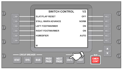
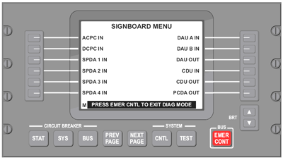
- On EMS CDU No. 1, select the diagnostic mode.
- Select SYSTEM - CNTL key (page 1/3)
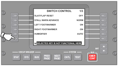
- Select lower left side key.
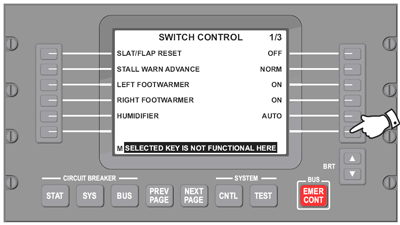
- Select lower right side key.
- On EMS CDU No. 1, select CIRCUIT BREAKER - SYS key and counters.
- SPDA 1 IN= 0=loss of communication from SPDA No. 1 to EMS CDU No. 1
- PCDA OUT= 0=loss of communication from EMS CDU No. 1 to ACPC, DCPC, SPDA 1, SPDA 2, SPDA 3, SPDA 4 and EMS CDU 2.
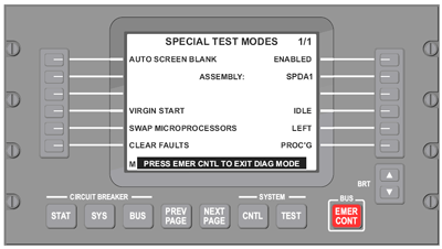
- On EMS CDU No. 1, select the diagnostic mode.
Quick Links:
| Removal of the Junction Box JB3 | AMM 24-00-01-000-801 [ Global Express ] [ G5000 ] [ Global XRS ] |
| Installation of the Junction Box JB3 | AMM 24-00-01-400-801 [ Global Express ] [ G5000 ] [ Global XRS ] |
| Removal of the Junction Box JB3 Circuit-Cards | AMM 24-00-02-000-801 [ Global Express ] [ G5000 ] [ Global XRS ] |
| Installation of the Junction Box JB3 Circuit-Cards | AMM 24-00-02-400-801 [ Global Express ] [ G5000 ] [ Global XRS ] |
| Removal of the DC Power Center (DCPC) | AMM 24-61-00-000-801 [ Global Express ] [ G5000 ] [ Global XRS ] |
| Installation of the DC Power Center (DCPC) | AMM 24-61-00-400-801 [ Global Express ] [ G5000 ] [ Global XRS ] |
| Removal of the Secondary-Power Distribution Assemblies | AMM 24-62-01-000-801 [ Global Express ] [ G5000 ] [ Global XRS ] |
| Installation of the Secondary-Power Distribution Assemblies | AMM 24-62-01-400-801 [ Global Express ] [ G5000 ] [ Global XRS ] |
| Removal of the Electrical Management System Control-and-Display Units (EMS CDU) | AMM 24-70-01-000-801 [ Global Express ] [ G5000 ] [ Global XRS ] |
| Installation of the Electrical Management System Control-and-Display Units (EMS CDU) | AMM 24-70-01-400-801 [ Global Express ] [ G5000 ] [ Global XRS ] |
| Wire Repair - Maintenance Practices - ALL | SPM 20-12-10-02 [ Global Express ] [ G5000 ] [ Global XRS ] |
Troubleshooting Recommendations:
- Swap EMS CDU 1 with EMS CDU 2.
- If system checks are good, replace EMS CDU 1 and do close out.
- If fault remains, continue with next step.
- Swap the SPDA 1 with SPDA 3.
- If system checks are good, replace SPDA 1 and do close out.
- If fault remains, continue with next step.
- Perform wiring checks between EMS CDU 1 and SPDA 1, SPDA 4, SPDA 2, DCPC, ACPC and SPDA 3.
- If wiring checks are not good, repair defective wiring as required and do close out.
- If wiring checks are good, continue with next step.
- Replace JB3 PCB3/JB3.
- Do close out.