

12/07/23
Message Overview:
Message Name:
TS1L - SENSOR FUEL TEMP/WRG FAULT
Message Code:
2844601PK
| Reporting LRU: | Fuel Management and Quantity Gauging Computer (FMQGC) |
| Associated CAS: | FUEL TEMP SENSOR (Caution) |
| System Description: | 28-41-00 - Fuel Management and Quantity Gauging System |
| Schematic Diagram: | [ G5000 ] [ Global Express ] [ Global XRS ] SSM 28-41-00-101 - Fuel Management and Quantity Gauging System (FMQGS) |
| Wiring Diagram: | [ G5000 ] [ Global Express ] [ Global XRS ] WM 28-41-00-1_001 - Sheet 1 - Fuel Computer - [9002-9084 PRE SB 700-28-029] [ G5000 ] [ Global Express ] [ Global XRS ] WM 28-41-01-1_001 - Sheet 1 - Fuel Computer - ALL |
Message Description:
TS1L SENSOR, FUEL TEMP/WRG FAULT shows when:
- Temperature Sensor is out of range (-60°C to +70°C)
- Temperature Sensor circuit is open
- Temperature Sensor circuit is shorted
Possible Causes:
- Left Temperature Sensor 1 (TS1L) (E34)
- Fuel Management and Quantity Gauging Computer (FMQGC) (A47)
- Associated Wiring
Troubleshooting Tips:
Advisory Wire/Service Bulletin:
- AW700-45-0065 - CAIMS Nuisance Fault Messages
Forum Articles/Infoservice/Newsletter: None
Flight Operation Notifications Manual (FONM): None
Quick Links:
| Removal of the Computer | [ G5000 ] [ Global Express ] [ Global XRS ] AMM28-41-01-000-801 |
| Installation of the Computer | [ G5000 ] [ Global Express ] [ Global XRS ] AMM28-41-01-400-801 |
| Removal of the Temperature Sensors | [ G5000 ] [ Global Express ] [ Global XRS ] AMM28-41-25-000-801 |
| Installation of the Temperature Sensors | [ G5000 ] [ Global Express ] [ Global XRS ] AMM28-41-25-400-801 |
| Wire Repair - Maintenance Practices - ALL | [ G5000 ] [ Global Express ] [ Global XRS ] SPM20-12-10-02 |
Troubleshooting Recommendations:
- Remove the FMQGC and inspect all connectors and pins on the unit and A/C side. Rerack the FMQGC and make sure it is fully and properly pushed into place. Is the fault still present?
- If NO, do close out.
- If YES, continue with next step.
- Remove the FMQGC and perform a resistance check as follows and compare results to the resistance chart below:
From To Result Expected Result A47AP1-A4 A47AP1-B4 See resistance chart A47AP1-A4 Ground Open A47AP1-B4 A47AP1-C4 Continuity A47AP1-B4 Ground Open - If the resistance values are within tolerance, replace the FMQGC and do close out.
- If the resistance values are not within tolerance, continue with next step.
TIPS: Better results are obtained if aircraft has been allowed to reach ambient temperature inside a hangar. Resistance results can be compared with the other fuel temperature sensors, they should be very close with each other.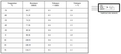
- Perform a wiring check between the left Temperature Sensor TS1L and the FMQGC. Look for continuity, short circuit and high resistance.
- If wiring checks are not good, repair defective wiring as required and do close out.
- If wiring checks are good, continue with next step.
TIP: It is recommended to start with the wiring checks that can be performed outside the fuel tank first. If a wiring defect is found outside the fuel tank, it will prevent you from having to prepare the fuel tank for access.
- Perform a visual inspection of the Temperature Sensor. Make sure it is exempt of damage, corrosion or contamination. Pay attention to the electrical connections.
- If defects are found, rectify as required and do close out.
- If checks are good, continue with next step.
- Interchange Temperature Sensor 1 with Temperature Sensor 2. Is the fault message still present?
- If NO, replace the defective Temperature Sensor and do close out.
- If YES, replace the FMQGC and continue with next step.
- Do close out.
