07/16/19
Message Overview:
Fault Message:
FMQGC CH B ELECT PWR/WRG
Fault Code:
2844675PK
Associated CAS:
| Reporting LRU: | Fuel Management and Quantity Gauging Computer (FMQGC) |
| System Description: | 28-41-00 |
| Schematic Diagram: | 28-41-00 [ Global Express ] [ G5000 ] [ Global XRS ] |
| Wiring Diagram: | 28-41-03 [ Global Express ] [ G5000 ] [ Global XRS ] |
Fault Description:
The Fuel Management and Quantity Gauging Computer (FMQGC) Channel B has an electrical power failure.
Possible Causes:
- Secondary Power Distribution Assembly (SPDA) 3 (A15)
- Fuel Management and Quantity Gauging Computer (FMQGC) (A47)
- Junction Box (JB6)
- Auxiliary Power Unit (APU) Starter Contactor Assembly (ACSA) (A48)
- Associated Wiring
Troubleshooting Tips:
Advisory Wire/Service Bulletin: None
Forum Articles/Infoservice/Newsletter: None
Loss of 28 VDC power source to the FMQGC CH B will set the FMQGS COMPUTER/WRG FAULT, FMQGS COMPUTER CH B LMS/WRG FAULT CAIMS messages, and the FUEL COMPUTR FAULT CAS messages. In addition, if the lost of power is caused by an SPDA 3 internal failure, the SPDA 3 FAILED CAIMS message will also be set.
Quick Links:
| Removal of the Junction Box JB6 | AMM 24-00-13-000-801 [ Global Express ] [ G5000 ] [ Global XRS ] |
| Installation of the Junction Box JB6 | AMM 24-00-13-400-801 [ Global Express ] [ G5000 ] [ Global XRS ] |
| Removal of the Junction Box JB6 Circuit-Cards | AMM 24-00-14-000-801 [ Global Express ] [ G5000 ] [ Global XRS ] |
| Installation of the Junction Box JB6 Circuit-Cards | AMM 24-00-14-400-801 [ Global Express ] [ G5000 ] [ Global XRS ] |
| Removal of the Secondary-Power Distribution Assemblies | AMM 24-62-01-000-801 [ Global Express ] [ G5000 ] [ Global XRS ] |
| Installation of the Secondary-Power Distribution Assemblies | AMM 24-62-01-400-801 [ Global Express ] [ G5000 ] [ Global XRS ] |
| Removal of the APU Starter-Contactor Assembly | AMM 24-62-05-000-801 [ Global Express ] [ G5000 ] [ Global XRS ] |
| Installation of the APU Starter-Contactor Assembly | AMM 24-62-05-400-801 [ Global Express ] [ G5000 ] [ Global XRS ] |
| Removal of the Computer | AMM 28-41-01-000-801 [ Global Express ] [ G5000 ] [ Global XRS ] |
| Installation of the Computer | AMM 28-41-01-400-801 [ Global Express ] [ G5000 ] [ Global XRS ] |
| Wire Repair - Maintenance Practices - ALL | SPM 20-12-10-02 [ Global Express ] [ G5000 ] [ Global XRS ] |
Troubleshooting Recommendations:
- Determine which FMQGC power source failed:
- If SPDA 3, when FMQGC is powered by selecting DC or AC power On in the cockpit, continue with next step.
- If ASCA, when the FMQGC is powered by turning ON the internal or external RDCP, go to step 6.
- On the EMS CDU, reset FMQGC CH B circuit breaker.
- If system checks are good, do close out.
- If fault remains, continue with next step.
- Using CAIMS, verify if the SPDA 3 FAILED (LEVEL A) fault message is displayed:
- If YES, continue with next step.
- If NO, go to step 6.
- Swap SPDA 3 with SPDA 4.
- If system checks are good, replace SPDA 3 and do close out.
- If fault remains, continue with next step.
- Perform wiring checks between FMQGC (A47FP1) and SPDA 3 (A15P3).
- If wiring checks are not good, repair defective wiring as required and do close out.
- If wiring checks are good, continue with next step.
- On the EMS CDU, reset FUEL R/D CH B circuit breaker.
- If system checks are good, do close out.
- If fault remains continue with next step.
- Using CAIMS, verify if messages concerning the ASCA are displayed:
- If YES, troubleshoot them first.
- If NO, continue with next step.
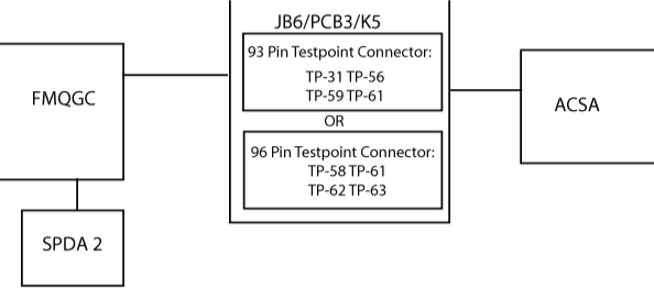
- For 93 Pin Test Point Connector, perform wiring checks via TP-31,TP-56,TP-59,TP-61 between JB6/PCB3/K5, APU starter-contactor assembly (A48P1) and FMQGC (A47CP1)/(A47FP1).
- If wiring checks are not good, repair defective wiring as required and do close out.
- If wiring checks are good, continue with next step.
- For 96 Pin Test Point Connector, perform wiring checks via TP-58,TP-61,TP-62,TP-63 between JB6/PCB3/K5, APU starter-contactor assembly (A48P1) and FMQGC (A47CP1)/(A47FP1).
- If wiring checks are not good, repair defective wiring as required and do close out.
- If wiring checks are good, continue with next step.
- Replace FMQGC.
- Do close out.