08/12/19
Message Overview:
Fault Message:
HYD PUMP 1B FAIL
Fault Code:
0000H1BF
Associated CAS:
| Reporting LRU: | Data Acquisition Unit (DAU) 2 |
| System Description: | 29-30-00 |
| Schematic Diagram: | 29-12-00 [ Global Express ] [ G5000 ] [ Global XRS ] |
| Wiring Diagram: | 29-00-03 [ Global Express ] [ G5000 ] [ Global XRS ] |
Fault Description:
Data Acquisition Unit (DAU) 2 is receiving an input that the Hydraulic Pressure Switch 1B is less than 1800 psi (low) with Hydraulic Pump Switch 1B selected to AUTO or ON.
NOTE: AC Motor Pump (ACMP) Pressure Switches close at 2400 psi (high) as pressure rises and opens at 1800 psi (low) as pressure decreases.
Possible Causes:
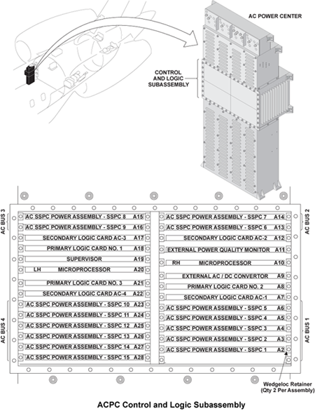
- AC Power Center (ACPC) Secondary Logic Card
- AC Motor Pump (ACMP) 1B (B51)
- Hydraulic Pressure Switch 1B
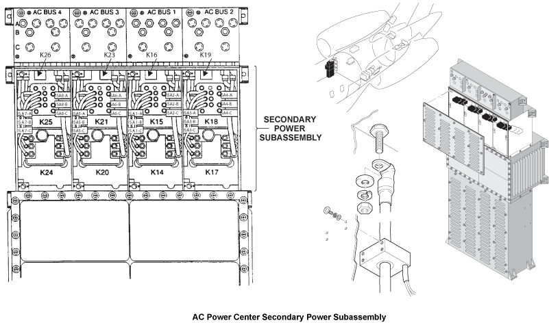
- AC Power Center (ACPC) (A54)
- Data Acquisition Unit (DAU) 2 (A18)
- Associated Wiring
Troubleshooting Tips:
Advisory Wire/Service Bulletin: None
Forum Articles/Infoservice/Newsletter: None
Quick Links:
| Quantity Check of the Hydraulic Fluid in the No. 1 and No. 2 Hydraulic Systems | AMM 12-12-00-610-801 [ Global Express ] [ G5000 ] [ Global XRS ] |
| Removal of the AC Power Center (ACPC) | AMM 24-51-00-000-801 [ Global Express ] [ G5000 ] [ Global XRS ] |
| Installation of the AC Power Center (ACPC) | AMM 24-51-00-400-801 [ Global Express ] [ G5000 ] [ Global XRS ] |
| Removal of the AC Power Center (ACPC) Secondary Logic | AMM 24-51-13-000-801 [ Global Express ] [ G5000 ] [ Global XRS ] |
| Installation of the AC Power Center (ACPC) Secondary Logic | AMM 24-51-13-400-801 [ Global Express ] [ G5000 ] [ Global XRS ] |
| Removal of the No. 1 and No. 2 Hydraulic-System AC-Motor-Driven Pumps | AMM 29-12-05-000-801 [ Global Express ] [ G5000 ] [ Global XRS ] |
| Installation of the No. 1 and No. 2 Hydraulic-System AC-Motor-Driven Pumps | AMM 29-12-05-400-801 [ Global Express ] [ G5000 ] [ Global XRS ] |
| Removal of the Hydraulic Pressure Transducers | AMM 29-31-01-000-801 [ Global Express ] [ G5000 ] [ Global XRS ] |
| Installation of the Hydraulic Pressure Transducers | AMM 29-31-01-400-801 [ Global Express ] [ G5000 ] [ Global XRS ] |
| Removal of the Hydraulic Pressure Switches | AMM 29-31-05-000-801 [ Global Express ] [ G5000 ] [ Global XRS ] |
| Installation of the Hydraulic Pressure Switches | AMM 29-31-05-400-801 [ Global Express ] [ G5000 ] [ Global XRS ] |
| Removal of the Data Acquisition Units (DAU) | AMM 31-42-01-000-801 [ Global Express ] [ G5000 ] [ Global XRS ] |
| Installation of the Data Acquisition Units (DAU) | AMM 31-42-01-400-801 [ Global Express ] [ G5000 ] [ Global XRS ] |
| Wire Repair - Maintenance Practices - ALL | SPM 20-12-10-02 [ Global Express ] [ G5000 ] [ Global XRS ] |
Troubleshooting Recommendations:
- Ensure Hydraulic System 1 is properly serviced.
- Operate Hydraulic Pump 1B and note Hydraulic System 1 pressure.
- If pump operates and pressure in below 2400 psi, replace ACMP 1B and do close out.
- If pump does not operate, go to step 4.
- If pump operates and pressure is above 2400 psi, continue with next step.
- Swap Hydraulic Pressure Switch 1B and 2B.
- If system checks are good, replace Hydraulic Pressure Switch 1B and do close out.
- If fault remains, go to step 9.
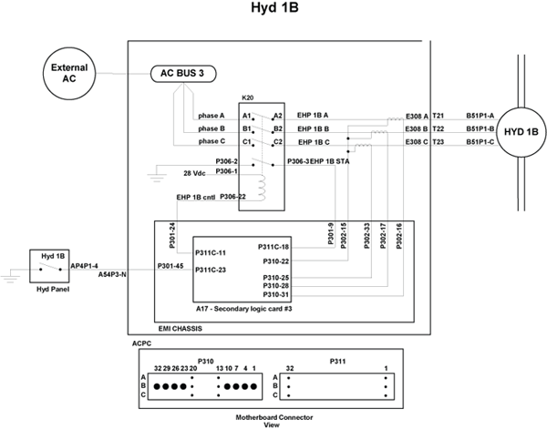
- Perform voltage check at ACMP 1B. Check for 115 VAC at connector B51P1 between pins A and E, pins B and E and pins C and E.
- If voltage is not present, go to step 6.
- If voltage is present, continue with next step.
- Remove enough clamps to swap ACMP 1B connector B51P1 and ACMP 2B connector B52P1.
- If system checks are good, replace ACMP 1B and do close out.
- If fault remains, continue with next step.
- Swap ACPC SLC AC 3 with SLC AC 2.
- If system checks are good, replace ACPC SLC AC 3 and do close out.
- If fault remains, continue with next step.
- Swap K20 relay with K17 relay in ACPC.
- If system checks are good, replace K20 relay and do close out.
- If fault remains, continue with next step.
- Perform wiring check between ACMP 1B, ACPC Relay K20, Hydraulic Pressure Switch 1B and DAU 2.
- If wiring checks are not good, repair defective wiring as required and do close out.
- If wiring checks are good, continue with next step.
- Swap DAU 2 with DAU 4.
- If system checks are good, replace DAU 2 and do close out.
- If fault remains, continue with next step.
- Accomplish check of EMI filter as shown below.
- Remove ACPC Secondary Logic Card 3.
- Measure the EMI Filter continuity from connector P310 pin 22 to aircraft structure.
- If reading is ground, replace the ACPC and do close out.
- If reading is open, continue with next step.
- Measure for open circuit between SLC 3, connector P310, pin 22 to pin 25, pin 28, and pin 31.
- If reading an open, replace the ACPC.
- Do close out.