09/09/19
Message Overview:
Fault Message:
[BMC1] X-WING VALVE CMD /X-WING VLV
Fault Code:
3615316BMC
Associated CAS:
| Reporting LRU: | Bleed Management Controller (BMC) |
| System Description: | 30-12-00 |
| Schematic Diagram: | 30-11-00 [ Global Express ] [ G5000 ] [ Global XRS ] |
| Wiring Diagram: | 30-11-03 [ Global Express ] [ G5000 ] [ Global XRS ] |
Fault Description:
The Cross Bleed Wing Anti-Ice Valve (or WAI Isolation Valve) position does not agree with the Bleed Management Controller (BMC) command. Inhibited during Take-Off Landing.
Possible Causes:
- Wing Cross Bleed Valve (L33)
- Secondary Power Distribution Assembly (SPDA) 4 (A16)
- Bleed Management Controller (BMC) 1 (A69)
- Junction Box JB3/PCB2
- Junction Box JB3/PCB3
- Junction Box JB3/PCB4
- Relay (K12)
- Associated Wiring
Troubleshooting Tips:
Advisory Wire/Service Bulletin:
- AW700-36-0365 - Bleed Management Controller - Data Gathering to Reduce No Fault Found (NFF) rate
Forum Articles/Infoservice/Newsletter:
- Forum Article 2011-VOL 8 issue 23 - Bleed Management Controller (BMC) Top 10 No Fault Found (NFF) vs. Reliability Improvement Modification Program (RIMP) implementation
- Questionnaire for replacing the BMC. Follow instructions using this (Fill out form)
NOTE: Always verify you are working with the current document revision. Access the CIC website to ensure the latest document revision.
NOTE: Before removing JB3, replace PCB3 or PCB4 Circuit Card if available.
NOTE: Use spare relay if available.
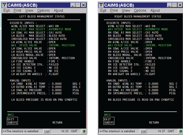
- CBW Valve position can be monitored in CAIMS.
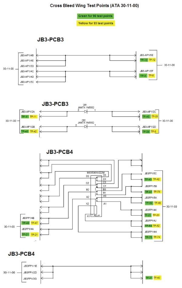
- Test Points are available in the Junction Box to monitor the different signals if needed.
Quick Links:
| Removal of the Junction Box JB3 Circuit-Cards | AMM 24-00-02-000-801 [ Global Express ] [ G5000 ] [ Global XRS ] |
| Installation of the Junction Box JB3 Circuit-Cards | AMM 24-00-02-400-801 [ Global Express ] [ G5000 ] [ Global XRS ] |
| Removal of the Secondary-Power Distribution Assemblies | AMM 24-62-01-000-801 [ Global Express ] [ G5000 ] [ Global XRS ] |
| Installation of the Secondary-Power Distribution Assemblies | AMM 24-62-01-400-801 [ Global Express ] [ G5000 ] [ Global XRS ] |
| Removal of the Cross-Bleed Valve | AMM 36-11-29-000-801 [ Global Express ] [ G5000 ] [ Global XRS ] |
| Installation of the Cross-Bleed Valve | AMM 36-11-29-400-801 [ Global Express ] [ G5000 ] [ Global XRS ] |
| Removal of the Bleed Management Controller | AMM 36-11-33-000-801 [ Global Express ] [ G5000 ] [ Global XRS ] |
| Installation of the Bleed Management Controller | AMM 36-11-33-400-801 [ Global Express ] [ G5000 ] [ Global XRS ] |
| Wire Repair - Maintenance Practices - ALL | SPM 20-12-10-02 [ Global Express ] [ G5000 ] [ Global XRS ] |
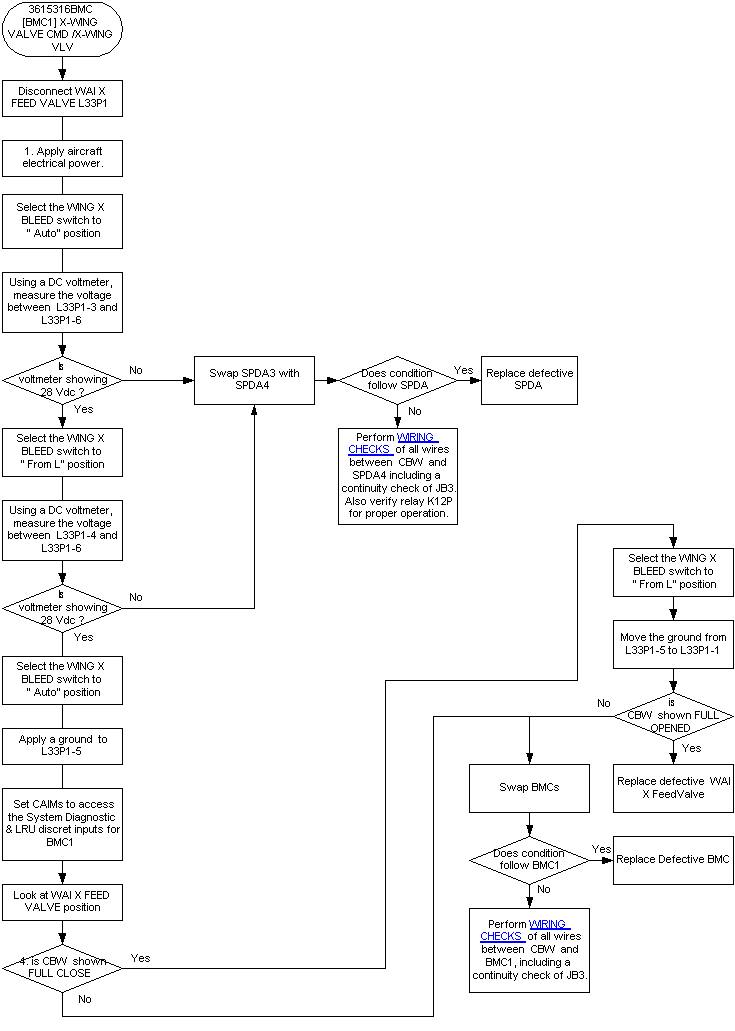
Troubleshooting Recommendations:
- Disconnect L33P1 from the CBW.
- With A/C power on, select the XBLEED switch to "CLSD".
- Using a multimeter, measure for 28 VDC at Wing Cross Bleed Valve connector L33P1 as follows:
From To Expected Result Result L33P1-3 L33P1-6 28 VDC - If there is no 28 VDC, go to step 11.
- If there is 28 VDC, continue with next step.
- Select WING XBLEED switch to "AUTO" and measure for 28 VDC at Wing Cross Bleed Valve connector L33P1 as follows:
From To Expected Result Result L33P1-4 L33P1-6 28 VDC - If NO, go to step 11.
- If YES, continue with next step.
- Select WING XBLEED switch to "FROM L" and connect a ground to L33P1-5.
- In CAIMS, go to "SYSTEM DIAG", Chap. 36, BMC1, "LRU TEST" and on Discrete & Analog input data page, check position of Wing Cross Bleed Valve,
- If NO, go to step 8.
- If indicated "FULL CLOSED", continue with next step.
- Select WING XBLEED switch to "AUTO", remove the ground from L33P1-5 and connect to L33P1-1. On Discrete & Analog input data page, check position of Wing Cross Bleed Valve.
- If indicated "FULL OPEN", replace defective WING XBLEED VALVE and do close out.
- If NO, continue with next step.
- Swap BMC1 and BMC2,
- If system checks are good, replace BMC1 and do close out.
- If fault remains, continue with next step.
- Perform wiring checks of all wires between BMC1 and the WING XBLEED VALVE.
- If wiring checks are not good, repair defective wiring as required and do close out.
- If wiring checks are good, continue with next step.
- Replace JB3/PCB4.
- If system checks do close out.
- If fault remains, continue with next step.
- Swap SPDA4 and SPDA3.
- If system checks are good, replace SPDA4 and do close out.
- If fault remains, continue with next step.
- Perform wiring checks of all wires between SPDA4 and the XBLEED VALVE.
- If wiring checks are not good, repair defective wiring as required and go to step 13.
- If wiring checks are good, continue with next step.
- Replace JB3/PCB2 or JB3/PCB3. Also verify relay K12P1 for proper operation.
- Do close out.
Troubleshooting Flow Chart