09/09/19
Message Overview:
Fault Message:
RIGHT COWL AI VALVE CMD /R CAIV
Fault Code:
3616315BMC
Associated CAS:
| Reporting LRU: | Bleed Management Controller (BMC) 2 |
| System Description: | 30-21-00 |
| Schematic Diagram: | 30-21-00 [ Global Express ] [ G5000 ] [ Global XRS ] |
| Wiring Diagram: | 36-11-02 [ Global Express ] [ G5000 ] [ Global XRS ] |
Fault Description:
The Right Cowl Anti-Ice Valve position reported to the Bleed Management Controller (BMC) does not agree with the R COWL ANTI-ICE Switch position or does not regulate the pressure properly. Inhibited during Take-off and Landing.
Possible Causes:
- Right Engine Cowl Anti-Ice Valve (CAIV)
- Bleed Air Control Panel (AP8)
- R Cowl Anti-Ice Switch (S11)
- Cowl Anti-Ice Relay (K1)
- Cowl Anti-Ice Relay (K2)
- Ice Detector 1 (E48)
- Ice Detector 2 (E49)
- Right Engine Cowl Anti-Ice Pressure Sensor
- Right Engine In-line Pressure Regulator Valve
- Cowl Anti-Icing Pressure Transducer
- Bleed Management Controller (BMC) 2 (A70)
- Associated Wiring
Troubleshooting Tips:
Advisory Wire/Service Bulletin:
- AW700-36-0365 - Bleed management controller - Data Gathering to reduce No Fault Found (NFF) rate
Forum Articles/Infoservice/Newsletter:
- Forum Article 2011-VOL 8 issue 23 - Bleed Management Controller (BMC) Top 10 No Fault Found (NFF) vs. Reliability Improvement Modification Program (RIMP) implementation
NOTE: Make sure the BMC Questionnaire is filled out and sent to Bombardier.
CAIV Position and Status Logic (used for synoptic page).
Quick Links:
| Removal of the Cowl Anti-Icing Valve | AMM 30-21-01-000-801 [ Global Express ] [ G5000 ] [ Global XRS ] |
| Installation of the Cowl Anti-Icing Valve | AMM 30-21-01-400-801 [ Global Express ] [ G5000 ] [ Global XRS ] |
| Removal of the Ice Detectors | AMM 30-81-01-000-801 [ Global Express ] [ G5000 ] [ Global XRS ] |
| Installation of the Ice Detectors | AMM 30-81-01-400-801 [ Global Express ] [ G5000 ] [ Global XRS ] |
| Removal of the Bleed Management Controller | AMM 36-11-33-000-801 [ Global Express ] [ G5000 ] [ Global XRS ] |
| Installation of the Bleed Management Controller | AMM 36-11-33-400-801 [ Global Express ] [ G5000 ] [ Global XRS ] |
| Removal of the forward Anti-Ice Air Duct | EMM 30-21-05-000-801 [ Global Express ] [ G5000 ] [ Global XRS ] |
| Installation of the forward Anti-Ice Air Duct | EMM 30-21-05-400-801 [ Global Express ] [ G5000 ] [ Global XRS ] |
| In-line Pressure Regulator Valve P/N 540-1394-2 | EIPC 30-21-05-01 [ Global Express ] [ G5000 ] [ Global XRS ] |
| Remove the Thermal Anti-Icing System | PPBU 71-00-02-604 [ Global Express ] [ G5000 ] [ Global XRS ] |
| Install the Thermal Anti-Icing System | PPBU 71-00-02-424 [ Global Express ] [ G5000 ] [ Global XRS ] |
| Wire Repair - Maintenance Practices - ALL | SPM 20-12-10-02 [ Global Express ] [ G5000 ] [ Global XRS ] |
Troubleshooting Recommendations:
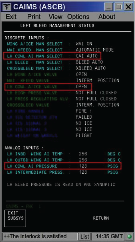
- On the PMAT, access CAIMS -> SYSTEM DIAG -> ATA 36 -> Select BMC 2 -> LRU TEST -> R BMC Discrete & analog input data. On the Bleed Air Control panel, set the R CAIV switch to all three positions consecutively while observing the CAIMS BMC data page.
- If the switch position displayed on the data page does not match with the actual switch position, go to step 22.
- When compared with the left side data page (BMC 1), if the RH COWL AI Pressure displayed on the data page is not correct, go to step 26.
- If the Cowl A/Ice Valve position displayed on the data page does not match the actual position of the CAIV, continue with next step.
NOTE: If engine is off, the CAIV has to be in the OPEN position, independent of switch position.
- Check if fault code 3616315BMC was set on ground.
- If NO, go to step 8.
- If YES, continue with next step.
- Ensure the engine has been shut down at least for 1 minute and the Cowl Anti-Ice Valve switch is selected OFF.
- Is the R COWL A/ICE FAULT advisory CAS message still present?
- If NO, no further action required. Do close out.
- If YES, continue with next step.
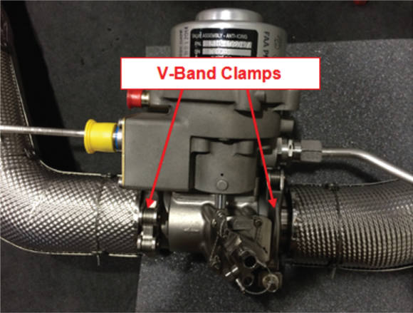
- Open the COWL doors and locate the CAIV.
- Check the CAIV V-Band clamps position.
- If the V-Band clamps are not installed 90 degrees off-set from each other, re-orientate the V-Band clamps so that they are oriented 90 degrees from each other.
- If the V-Band clamps are installed 90 degrees off-set from each other, continue with next step.
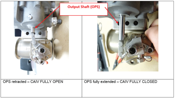
- Verify the valve butterfly position by observing the Output Shaft (OPS) position.
- If the OPS is retracted and the CAIV is displayed CLOSED on the Bleed Air/Anti-Ice synoptic page, go to step 9.
- If the OPS is fully extended, replace the CAIV and do close out.
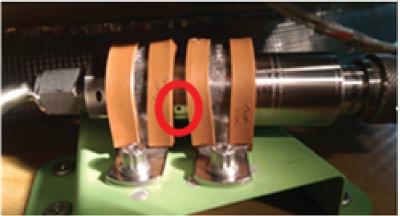
- Check the Pressure Transducer vent hole for installation clamp obstruction. Obstructing the Pressure Transducer vent hole will result in false pressure measurements and the display of CAI error messages.
- If the Pressure Transducer vent hole is covered by the installation clamps, rectify as required (see image below) and do close out.
- If the Pressure Transducer vent hole is not obstructed, continue with next step.
- Swap Right CAIV with Left CAIV.
- If the system checks are good, replace Right CAIV and do close out.
- If fault remains, continue with next step.
- Disconnect the right CAIV connector P720. On the Bleed Air control Panel, set the R CAIV switch to "ON". Make sure there is no voltage at P720-1.
- If there is voltage, continue with next step.
- If there is no voltage, go to step 12.
- Perform a wiring check between the CAIV and the Bleed Air Control Panel.
- If wiring checks are good, check/replace the R CAIV Switch and do close out.
- If wiring checks are not good, repair defective wiring as required and do close out.
- On the Bleed Air control Panel, set the R CAIV switch to "OFF". Make sure there is 28 VDC at P720-1.
- If there is no voltage, continue with next step.
- If there is 28 VDC, go to step 14.
- Perform a wiring check between the CAIV and the Bleed Air Control Panel.
- If wiring checks are good, go to step 20.
- If wiring checks are not good, repair defective wiring as required and do close out.
- Disconnect CAIV connector P719 and P720. Disconnect BMC 2 connector A70P1. Perform a continuity check as follows:
From To Expected Result Result P719-3 Ground Open P719-4 Ground Continuity P719-5 Ground Continuity P720-2 Ground Continuity P720-3 Ground Continuity - If the checks are good, continue with next step.
- If the checks are not good, repair defective wiring as required and do close out.
- Perform a continuity check as follows:
From To Result P719-3 A70P1-13 - If there is continuity, continue with next step.
- If there is no continuity, repair defective wiring as required and do close out.
- Disconnect Bleed Air Control Panel connectors AP8P3 and AP8P4. Perform a continuity check as follows:
From To Result AP8P3-32 Ground AP8P4-32 Ground - If there is continuity on AP8P4-32, go to step 18.
- If there is no continuity, go to step 19.
- If there is continuity on AP8P3-32, continue with next step.
- Disconnect the Left Ice detector connector E48P1. Perform a continuity check as follows:
From To Result AP8P3-32 Ground - If there is continuity, repair defective wiring as required and do close out.
- If there is no continuity, replace the Left Ice Detector and do close out.
- Disconnect the Right Ice detector connector E49P1. Perform a continuity check as follows:
From To Result AP8P4-32 Ground - If there is continuity, repair defective wiring as required and do close out.
- If there is no continuity, replace the Right Ice Detector and do close out.
- Disconnect the Left Ice detector connector E48P1 and the Right Ice detector connector E49P1. Perform a continuity check as follows:
From To Result AP8P3-32 E48P1-6 AP8P4-32 E49P1-6 - If there is no continuity, repair defective wiring as required and do close out.
- If there is continuity, continue with next step.
- Perform a 28 VDC voltage check on AP8P4-31. Is 28 VDC present?
- If YES, go to step 22.
- If NO, continue with next step.
- Make sure the R COWL A/ICE VLV circuit breaker is set to "IN" and perform wiring check between the Bleed Air Control Panel and SPDA 3.
- If wiring checks are not good, repair defective wiring as required and do close out.
- If wiring checks are good, continue with next step.
- Perform a continuity check directly on the Bleed Air Control Panel as follows:
From To Expected Result Result R CAIV Switch position "ON" AP8J4-31 AP8J4-33 Open AP8J4-27 AP8J3-25 Continuity AP8J4-28 AP8J3-25 Open R CAIV Switch position "OFF" AP8J4-31 AP8J4-33 Continuity AP8J4-27 AP8J3-25 Open AP8J4-28 AP8J3-25 Continuity R CAIV Switch position "AUTO" AP8J4-31 AP8J4-33 Continuity AP8J4-31 AP8J4-32 AP8 K2 Coil resistance AP8J4-27 AP8J3-25 Open AP8J4-28 AP8J3-25 Open - If the results are as per the table above, go to step 24.
- If the results are not as per the table above, continue with next step.
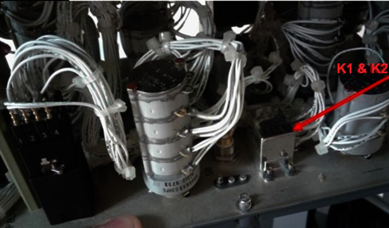
- Test the internal wiring of the panel, the R CAIV switch and the two relays (K1 and K2).
- If defects are suspected with the K1 or K2 relays, continue with next step.
- If defects are suspected with R CAIV switch, replace R CAIV switch and do close out.
- Perform a continuity check as follows:
For K1From To Expected result Result X1 X2 Continuity A2 A3 Continuity C1 C2 Open D2 D3 Continuity For K2
From To Expected result Result X1 X2 Continuity B2 B3 Continuity A1 A2 Open D2 D3 Continuity - If results are not as in the tables above, replace defective relay(s) as required and do close out.
- If the test results are as expected, continue with next step.
- Please note that it is possible a contact is "tack welded" in the de-energized position.
- If it is the case, only a test performed with power can reveal the defect.
- If it is not the case, continue with next step.
- Swap the right and left Cowl Anti-Ice Pressure transducers.
- If the system checks are good, replace right pressure transducer and do close out.
- If fault remains, continue with next step.
- Disconnect CAI Pressure transducer connector P718. Using a voltmeter, make sure there is 28 VDC at P718-1.
- If there is 28 VDC, go to step 29.
- If there is no voltage, continue with next step.
- Check to make sure R BMC SENSORS circuit breaker is "IN" and perform wiring checks between the Pressure sensor and SPDA 3.
- If wiring checks are not good, repair defective wiring as required and do close out.
- If wiring checks are good, continue with next step.
- Disconnect BMC 2 connector A70P1. Perform a continuity check as follows:
From To Expected Result Result P718-4 Ground Continuity P718-5 Ground Continuity P718-2 Ground Open P718-3 Ground Open - If the checks are good, continue with next step.
- If the checks are not good, repair defective wiring as required and do close out.
- Perform a continuity check as follows:
From To Result P718-2 A70P1-1 P718-3 A70P1-6 - If there is no continuity, repair defective wiring as required and do close out.
- If there is continuity, continue with next step.
- Perform troubleshooting of 3616425BMC.
- Swap BMC 2 with BMC 1. Is the fault still present?
- If NO, replace BMC 2 and do close out.
- If YES, continue with next step.
- Replace the in-line pressure regulator valve.
- Do close out.