04/24/25
Message Overview:
Message Name:
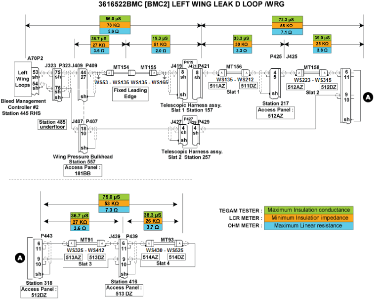
[BMC2] LEFT WING LEAK D LOOP /WRG
Message Code:
3616522BMC
| Reporting LRU: | Bleed Management Controller 2 (BMC) |
| Associated CAS: | L WING A/ICE FAIL (Caution) WING A/ICE FAULT (Advisory) |
| System Description: | 36-12-00 - Bleed-Air Leak-Detection System |
| Schematic Diagram: | [ G5000 ] [ Global Express ] [ Global XRS ] SSM 36-12-00-101 - Bleed Air Leak Detection System - Electrical Schematic |
| Wiring Diagram: | [ G5000 ] [ Global Express ] [ Global XRS ] WM 36-12-00-3_001 - Sheet 1 - Left Wing Leading Edge - [9002] [ G5000 ] [ Global Express ] [ Global XRS ] WM 36-12-01-1_001 - Sheet 1 - Wing Leading Edge (Left) - ALL |
Message Description:
The Left Wing Anti-Ice (A/ICE) Loop circuit connected to Bleed Management Controller 2 (BMC) has been detected with an Open Center Conductor or short circuit between the Center Conductor and the outer sheath. Inhibited during Take-Off and Landing.
Possible Causes:
- Bleed Management Controller 2 (BMC) (A70)
- Left Wing Loop Detect Loop Fixed Wing (MT154)
- Left Wing Loop Detect Loop Fixed Wing (MT155)
- Left Wing Loop Detect Loop Slat 1 (MT156)
- Left Wing Loop Detect Loop Slat 2 (MT158)
- Left Wing Loop Detect Loop Slat 3 (MT91)
- Left Wing Loop Detect Loop Slat 4 (MT93)
- Associated Wiring
Troubleshooting Tips:
Advisory Wire/Service Bulletin:
- AW700-30-0292 - Ice Detector Removals Due to Generator Switching
- AW700-36-0365 - Bleed Management Controller - Data Gathering to Reduce No Fault Found (NFF) Rate
- AW700-36-0826 - Kidde Bleed Leak Detection Loops Notice of Escape
- SB700-30-020 - Modification - Wing Anti-Icing System - Introduction of Improved Telescopic Wiring for the Leading Edge and Slat
Full Throttle Blog/Forum Articles/Infoservice/Newsletter:
- Forum Article 2011-VOL 8 issue 23 - Bleed Management Controller (BMC) Top 10 No Fault Found (NFF) vs. Reliability Improvement Modification Program (RIMP) implementation.
- Questionnaire for replacing the BMC. Follow instructions using this (Fill out form).
Flight Operation Notifications Manual (FONM): None
NOTES:
- Always verify you are working with the current document revision. Access the CIC website to ensure the latest document revision.
- The sensing element is used to find a temperature that is too hot. When the eutectic salt is heated to its alarm temperature, it forms a conductive path between the center wire conductor and the outer sheath of the sensing element. This path transmits a signal that gives an alarm signal to the detection circuit.
- Let the temperature of the sensing element become stable at ambient room temperature. Write the temperature.
- To prevent damage to the sensing element connector, install test pins in the connectors when you do the continuity and insulation resistance tests.
CAUTION:
- WHEN PERFORMING THE CONDUCTANCE TEST OF THE LEAK DETECTION LOOPS, DO NOT USE A METER THAT APPLIES DC VOLTAGE. DO NOT USE INSULATION RESISTANCE “MEGGER” TESTERS OR DIELECTRIC VOLTAGE “HYPOT” TESTERS. THESE WILL DAMAGE THE SENSING ELEMENT.
- DO NOT DO TESTS OF A SENSING ELEMENT THAT IS HEATED TO WITHIN 100°F (55°C) OF ITS ALARM TEMPERATURE
Quick Links:
| Grounding of the Aircraft | [ G5000 ] [ Global Express ] [ Global XRS ] AMM10-11-00-867-801 |
| Removal of the Covers and Plugs | [ G5000 ] [ Global Express ] [ Global XRS ] AMM10-12-00-020-801 |
| Installation of the Covers and Plugs | [ G5000 ] [ Global Express ] [ Global XRS ] AMM10-12-00-420-801 |
| Standard Aircraft Configuration for Maintenance | [ G5000 ] [ Global Express ] [ Global XRS ] AMM12-00-00-867-801 |
| Aircraft Walkaround (for Maintenance) | [ G5000 ] [ Global Express ] [ Global XRS ] AMM12-00-00-867-802 |
| Connect Electrical Power to the Aircraft | [ G5000 ] [ Global Express ] [ Global XRS ] AMM24-00-00-861-801 |
| Remove the Electrical Power from the Aircraft | [ G5000 ] [ Global Express ] [ Global XRS ] AMM24-00-00-861-802 |
| Electrical/Electronic Safety Precautions | [ G5000 ] [ Global Express ] [ Global XRS ] AMM24-00-00-910-801 |
| Electrostatic Discharge Safety Precautions | [ G5000 ] [ Global Express ] [ Global XRS ] AMM24-00-00-910-802 |
| Removal of the Bleed Management Controller | [ G5000 ] [ Global Express ] [ Global XRS ] AMM36-11-33-000-801 |
| Installation of the Bleed Management Controller | [ G5000 ] [ Global Express ] [ Global XRS ] AMM36-11-33-400-801 |
| Operational Test of the Bleed Management Controller | [ G5000 ] [ Global Express ] [ Global XRS ] AMM36-11-33-710-801 |
| Bleed Leak-Detection-Loops and Components Maintenance Practices | [ G5000 ] [ Global Express ] [ Global XRS ] AMM36-12-00-910-801 |
| Operational Test of the Bleed Leak-Detection-Loops | [ G5000 ] [ Global Express ] [ Global XRS ] AMM36-12-01-710-801 |
| Removal of the Slat Access Panels (from 511AZ/611AZ to 514DZ/614DZ) | [ G5000 ] [ Global Express ] [ Global XRS ] AMM57-42-01-000-802 |
| Installation of the Slat Access Panels (from 511AZ/611AZ to 514DZ/614DZ) | [ G5000 ] [ Global Express ] [ Global XRS ] AMM57-42-01-400-802 |
| Access to Active Faults | [ G5000 ] [ Global Express ] [ Global XRS ] AMM45-45-00-970-802 |
| Access to Stored Faults | [ G5000 ] [ Global Express ] [ Global XRS ] AMM45-45-00-970-803 |
| Access to System Diagnostics | [ G5000 ] [ Global Express ] [ Global XRS ] AMM45-45-00-970-804 |
| Flight Deck Effect to Fault Correlations | [ G5000 ] [ Global Express ] [ Global XRS ] AMM45-45-00-970-821 |
| Wire Repair - Maintenance Practices - ALL | [ G5000 ] [ Global Express ] [ Global XRS ] SPM20-12-10-02 |
Troubleshooting Recommendations:
- Disconnect A70P2 from BMC 2.
- Measure Insulation resistance and line resistance of the detection loops as per the Leak Detection Elements troubleshooting sheet. Make sure line resistance and insulation values are within the specified limits.
NOTE: Please be aware that the outer conductor of the wires going to the telescopic duct harness connectors are connected to the back shell/shield instead of a pin as shown in the wiring schematic in this procedure for aircraft 9161 and subs and aircraft post SB700-30-020.- If the values are within specified limits, go to step 4.
- If values are not within the specified limits, continue with next step.
- Replace faulty elements.
- If system checks are good, do close out.
- If fault remains, continue with next step.
- Make sure the Leak Detection Elements are installed as per Bleed Air Leak Detection System - Maintenance Practices.
- If system checks are good, do close out.
- If fault remains, continue with next step.
- Perform wiring checks of the remaining wires linking the Left WING A/ICE Loops circuit to BMC 2.
- If wiring checks are not good, repair defective wiring as required and do close out.
- If wiring checks are good, continue with next step.
- Replace BMC 2.
- Do close out.