04/24/25
Message Overview:
Message Name:
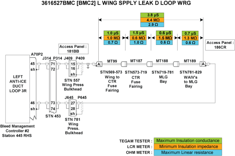
[BMC2] L WING SPPLY LEAK D LOOP/WRG
Message Code:
3616527BMC
| Reporting LRU: | Bleed Management Controller 2 (BMC) |
| Associated CAS: | L WING A/ICE FAIL (Caution) WING A/ICE FAULT (Advisory) |
| System Description: | 36-12-00 - Bleed-Air Leak-Detection System |
| Schematic Diagram: | [ G5000 ] [ Global Express ] [ Global XRS ] SSM 36-12-00-101 - Bleed Air Leak Detection System - Electrical Schematic |
| Wiring Diagram: | [ G5000 ] [ Global Express ] [ Global XRS ] WM 36-12-00-1_003 - Sheet 3 - Center/AFT Fuselage - [9004-9024] [ G5000 ] [ Global Express ] [ Global XRS ] WM 36-12-03-1_001 - Sheet 1 - Centre/Aft Fuselage - ALL |
Message Description:
The Left Wing Supply (SPPLY) Loop circuit connected to Bleed Management Controller 2 (BMC) has been detected with an Open Center Conductor or short circuit between the Center Conductor and the Outer Sheath. Inhibited during Take-Off and Landing.
Possible Causes:
- Bleed Management Controller 2 (BMC) (A70)
- Left Anti-Ice Duct Loop E (MT99)
- Left Anti-Ice Duct Loop F (MT187)
- Left Anti-Ice Duct Loop G (MT188)
- Left Anti-Ice Duct Loop H (MT189)
- Associated Wiring
Troubleshooting Tips:
Advisory Wire/Service Bulletin:
- AW700-36-0365 - Bleed Management Controller - Data Gathering to Reduce No Fault Found (NFF) Rate
Full Throttle Blog/Forum Articles/Infoservice/Newsletter:
- Infoservice_Global_Dec_1999.pdf - Wing Anti-Ice Fault Spurious EICAS Messages (Dec/1999)
- Forum Article 2011-VOL 8 issue 23 - Bleed Management Controller (BMC) Top 10 No Fault Found (NFF) vs. Reliability Improvement Modification Program (RIMP) implementation
Flight Operation Notifications Manual (FONM): None
NOTES:
- Always verify you are working with the current document revision. Access the CIC website to ensure the latest document revision.
- Questionnaire for replacing the BMC. Follow instructions using this (Fill out form).
Quick Links:
| Grounding of the Aircraft | [ G5000 ] [ Global Express ] [ Global XRS ] AMM10-11-00-867-801 |
| Removal of the Covers and Plugs | [ G5000 ] [ Global Express ] [ Global XRS ] AMM10-12-00-020-801 |
| Installation of the Covers and Plugs | [ G5000 ] [ Global Express ] [ Global XRS ] AMM10-12-00-420-801 |
| Standard Aircraft Configuration for Maintenance | [ G5000 ] [ Global Express ] [ Global XRS ] AMM12-00-00-867-801 |
| Aircraft Walkaround (for Maintenance) | [ G5000 ] [ Global Express ] [ Global XRS ] AMM12-00-00-867-802 |
| Connect Electrical Power to the Aircraft | [ G5000 ] [ Global Express ] [ Global XRS ] AMM24-00-00-861-801 |
| Remove the Electrical Power from the Aircraft | [ G5000 ] [ Global Express ] [ Global XRS ] AMM24-00-00-861-802 |
| Electrical/Electronic Safety Precautions | [ G5000 ] [ Global Express ] [ Global XRS ] AMM24-00-00-910-801 |
| Electrostatic Discharge Safety Precautions | [ G5000 ] [ Global Express ] [ Global XRS ] AMM24-00-00-910-802 |
| Removal of the Bleed Management Controller | [ G5000 ] [ Global Express ] [ Global XRS ] AMM36-11-33-000-801 |
| Installation of the Bleed Management Controller | [ G5000 ] [ Global Express ] [ Global XRS ] AMM36-11-33-400-801 |
| Operational Test of the Bleed Management Controller | [ G5000 ] [ Global Express ] [ Global XRS ] AMM36-11-33-710-801 |
| Bleed Leak-Detection-Loops and Components Maintenance Practices | [ G5000 ] [ Global Express ] [ Global XRS ] AMM36-12-00-910-801 |
| Operational Test of the Bleed Leak-Detection-Loops | [ G5000 ] [ Global Express ] [ Global XRS ] AMM36-12-01-710-801 |
| Access to Active Faults | [ G5000 ] [ Global Express ] [ Global XRS ] AMM45-45-00-970-802 |
| Access to Stored Faults | [ G5000 ] [ Global Express ] [ Global XRS ] AMM45-45-00-970-803 |
| Access to System Diagnostics | [ G5000 ] [ Global Express ] [ Global XRS ] AMM45-45-00-970-804 |
| Flight Deck Effect to Fault Correlations | [ G5000 ] [ Global Express ] [ Global XRS ] AMM45-45-00-970-821 |
| Wire Repair - Maintenance Practices - ALL | [ G5000 ] [ Global Express ] [ Global XRS ] SPM20-12-10-02 |
Troubleshooting Recommendations:
- Disconnect A70P2 from BMC 2.
- Measure Insulation resistance and line resistance of the detection loops as per the Leak Detection Elements troubleshooting sheet. Make sure line resistance and insulation values are within the specified limits.
- If the values are within specified limits, go to step 4.
- If values are not within the specified limits, continue with next step.
- Replace faulty elements.
- If system checks are good, do close out.
- If fault remains, continue with next step.
- Make sure the Leak Detection Elements are installed as per Bleed Air Leak Detection System - Maintenance Practices.
- If system checks are good, do close out.
- If fault remains, continue with next step.
- Perform wiring checks of the remaining wires linking the Left A/ICE DUCT Loops circuit to BMC2.
- If wiring checks are not good, repair defective wiring as required and do close out.
- If wiring checks are good, continue with next step.
- Replace BMC 2.
- Do close out.