

09/16/19
Message Overview:
Fault Message:
OPEN CKT - EGT SENSOR/CKT 1 WIRING
Fault Code:
4960149APU
Associated CAS:
| Reporting LRU: | Full-Authority Digital Engine-Controller (FADEC) |
| System Description: | 49-40-00 |
| Schematic Diagram: | 49-61-00 [ Global Express ] [ G5000 ] [ Global XRS ] |
| Wiring Diagram: | 49-12-00 [ Global Express ] [ G5000 ] [ Global XRS ] 49-61-01 [ Global Express ] [ G5000 ] [ Global XRS ] |
Fault Description:
The Exhaust Gas Temperature (EGT) Sensor 1 conditioning voltage in the Full Authority Digital Engine Control (FADEC) is out of range low and the signal read by the FADEC is out of range low. This shows a possible open in the EGT Sensor or wiring. This fault is shown when EGT Sensor 2 is not failed.
Possible Causes:
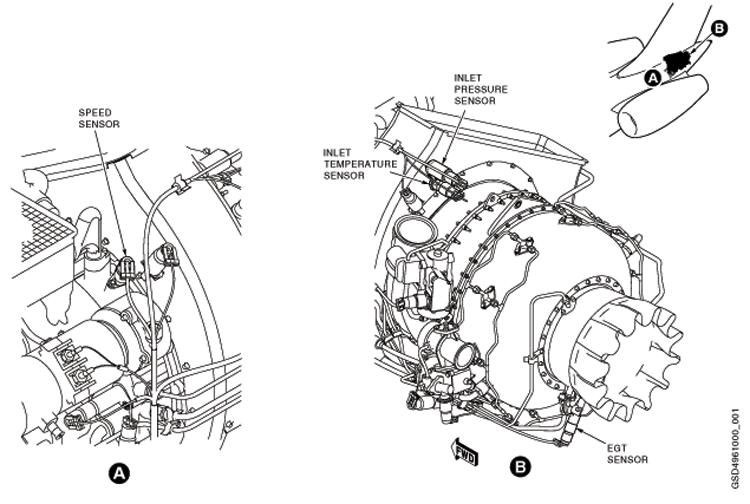
- Exhaust-Gas Temperature (EGT) Sensor (TC1)
- Auxiliary Power Unit (APU) Full-Authority Digital Engine-Controller (FADEC) (A108)
- Associated Wiring
Troubleshooting Tips:
Advisory Wire/Service Bulletin: None
Forum Articles/Infoservice/Newsletter:
- Honeywell SIL-APU-87 - AIRBORNE AUXILIARY POWER - GAS TURBINE ENGINE-RE220GX APU Auto Shutdown in Heavy Rain
If CAS message is not active, verify stored faults on CAIMS, under System Diagnostics, ATA 49 (this will include ground and air faults).
Quick Links:
| Access to Active Faults | AMM 45-45-00-970-802 [ Global Express ] [ G5000 ] [ Global XRS ] |
| Access to Stored Faults | AMM 45-45-00-970-803 [ Global Express ] [ G5000 ] [ Global XRS ] |
| Access to System Diagnostics | AMM 45-45-00-970-804 [ Global Express ] [ G5000 ] [ Global XRS ] |
| Removal of the Engine Branched Wiring-Harness | AMM 49-12-01-000-801 [ Global Express ] [ G5000 ] [ Global XRS ] |
| Installation of the Engine Branched Wiring-Harness | AMM 49-12-01-400-801 [ Global Express ] [ G5000 ] [ Global XRS ] |
| Removal of the Full-Authority Digital Engine-Controller (FADEC) |
AMM 49-61-01-000-801 [ Global Express ] [ G5000 ] [ Global XRS ] |
| Installation of the Full-Authority Digital Engine-Controller (FADEC) |
AMM 49-61-01-400-801 [ Global Express ] [ G5000 ] [ Global XRS ] |
| Removal of the Exhaust Gas Temperature (EGT) Sensor | AMM 49-61-05-000-801 [ Global Express ] [ G5000 ] [ Global XRS ] |
| Installation of the Exhaust Gas Temperature (EGT) Sensor | AMM 49-61-05-400-801 [ Global Express ] [ G5000 ] [ Global XRS ] |
| Wire Repair - Maintenance Practices - ALL | SPM 20-12-10-02 [ Global Express ] [ G5000 ] [ Global XRS ] |
Troubleshooting Recommendations:
- Visually inspect the EGT Sensors for signs of water that would cause a short between the posts. Use Honeywell SIL-APU-87 if needed to add more RTV.
- Inspect the wiring and connectors to the EGT sensor 1 for any damage, repair or replace as required.
- If there is any damage, repair or replace as required and do close out.
- If there is no damage, continue with next step.
- Inspect the EGT sensor 1 for condition and check that the resistance between the Alumel and Chromel terminal as follows:
From To Expected Result Result Alumel Chromel <20 ohms - If there is any damage, replace the EGT sensor 1 and do close out.
- If there is no damage, continue with next step.
- Re-rack FADEC and verify connector A108BP1-K6 and A108BP1-K5 for damage or FOD. Verify if fault is still present?
- If YES, repair defective wiring as required and do close out.
- If NO, continue with next step.
- Perform wiring checks between APU firewall connector (P802) and the EGT sensor 1 as follow:
From To Expected Result Result P802-11 Chromel <6 ohms P802-12 Alumel <6 ohms - If the wiring checks are not good, repair defective wiring as required and do close out.
- If the wiring checks are good, continue with next step.
- Perform wiring checks between APU firewall connector (J802) the APU FADEC connector (A108BP1).
From To Expected Result Result J802-11 A108BP1-K6 <11 ohms J802-12 A108BP1-K5 <11 ohms - If the wiring checks are not good, repair defective wiring as required and do close out.
- If the wiring checks are good, continue with next step.
- Replace APU FADEC.
- Do close out.