09/24/19
Message Overview:
Fault Message:
L IOP CH B WRG/FMU[IOP SOL]
Fault Code:
7325525LBR
Associated CAS:
| Reporting LRU: | Left Engine Electronic Controller (EEC) |
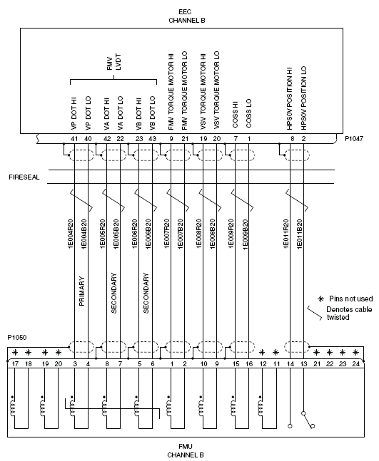
| System Description: | 73-20-00 |
| Schematic Diagram: | None |
| Wiring Diagram: | 71-50-01 [ Global Express ] [ G5000 ] [ Global XRS ] |
Fault Description:
There is an short circuit to ground on the high side of the Independent Overspeed Protection (IOP) Solenoid Coil (channel B).
NOTE: This incident can cause a secondary failure of the Engine Electronic Controller (EEC). Do not supply electrical power to the EEC until you correct this condition.
Possible Causes:
- Fuel Metering Unit (FMU)
- Left Engine Electronic Controller (EEC)
- Associated Wiring
Troubleshooting Tips:
Advisory Wire/Service Bulletin:
- AW700-45-0065 - CAIMS Nuisance Fault Messages
Forum Articles/Infoservice/Newsletter: None
Quick Links:
| Opening of the Cowls | AMM 71-10-00-010-801 [ Global Express ] [ G5000 ] [ Global XRS ] |
| Closing of the Cowls | AMM 71-10-00-410-801 [ Global Express ] [ G5000 ] [ Global XRS ] |
| Connection of Electrical Connectors | EMM 70-50-01-910-801 [ Global Express ] [ G5000 ] [ Global XRS ] |
| Removal of the Eng Electronic Controller (EEC) Mod 73-101559 |
EMM 73-21-01-000-801-B00 [ Global Express ] [ G5000 ] [ Global XRS ] |
| Installation of the Eng Electronic Controller (EEC) Mod 73-101559 |
EMM 73-21-01-400-801-B00 [ Global Express ] [ G5000 ] [ Global XRS ] |
| Removal of the Fuel Metering Unit | EMM 73-21-03-000-801 [ Global Express ] [ G5000 ] [ Global XRS ] |
| Installation of the Fuel Metering Unit | EMM 73-21-03-400-801 [ Global Express ] [ G5000 ] [ Global XRS ] |
| Wire Repair - Maintenance Practices - ALL | SPM 20-12-10-02 [ Global Express ] [ G5000 ] [ Global XRS ] |
Troubleshooting Recommendations:
- Perform a visual inspection of the interface wiring for damage between the EEC connector P1047 and the FMU connector P1050.
- If there is a damage, repair defective wiring as required and do close out.
- If there is no damage, continue with next step.
- Perform wiring checks between the EEC and the FMU.
- If wiring checks are not good, repair defective wiring as required and do close out.
- If wiring checks are good, continue with next step.
- Swap EEC 1 with EEC 2.
- If system checks are good, replace EEC 1 and do close out.
- If fault remains, continue with next step.
- Replace FMU.
- Do close out.