09/18/24
Message Overview:
Fault Message:
L FMU[COSS FAILURE]
Fault Code:
7325527LBR
Associated CAS:
| Reporting LRU: | Left Engine Electronic Controller (EEC) |
| System Description: | 73-20-00 |
| Schematic Diagram: | None |
| Wiring Diagram: | 71-50-01 [ Global Express ] [ G5000 ] [ Global XRS ] |
Message Description:
The Combined Overspeed and Shut-off Solenoid (COSS) in the Fuel Metering Unit (FMU) does not operate. This condition occurs when:
- The High Pressure Shut-Off Valve (HPSOV) does not agree with the selection
OR
- During Independent Overspeed Protection (IOP) checks
The FMU circuits are continuously monitored by the Full-Authority Digital Engine-Controller (FADEC).
Possible Causes:
- Fuel Metering Unit (FMU)
- Left Engine Electronic Controller (EEC)
- Throttle Quadrant Assembly (AP41)
- SPDA 4 (A16)
- Associated Wiring
Troubleshooting Tips:
Advisory Wire/Service Bulletin: None
Forum Articles/Infoservice/Newsletter: None
Flight Operation Notifications Manual (FONM): None
NOTES:
- This condition occurs when:
-The High Pressure Shut-Off Valve (HPSOV) does not agree with the selection.
-During Independent Overspeed Protection (IOP) checks. - The FMU circuits are continuously monitored by the FADEC.
Quick Links:
| Opening of the Cowls | AMM 71-10-00-010-801 [ Global Express ] [ G5000 ] [ Global XRS ] |
| Closing of the Cowls | AMM 71-10-00-410-801 [ Global Express ] [ G5000 ] [ Global XRS ] |
| Removal of the Throttle Quadrant | AMM 76-10-01-000-801 [ Global Express ] [ G5000 ] [ Global XRS ] |
| Installation of the Throttle Quadrant | AMM 76-10-01-400-801 [ Global Express ] [ G5000 ] [ Global XRS ] |
| Operational Test of FADEC System | EMM 73-21-00-710-801 [ Global Express ] [ G5000 ] [ Global XRS ] |
| Removal of the Eng Electronic Controller (EEC) Mod 73-101559 |
EMM 73-21-01-000-801-B00 [ Global Express ] [ G5000 ] [ Global XRS ] |
| Installation of the Eng Electronic Controller (EEC) Mod 73-101559 |
EMM 73-21-01-400-801-B00 [ Global Express ] [ G5000 ] [ Global XRS ] |
| Removal of the Fuel Metering Unit | EMM 73-21-03-000-801 [ Global Express ] [ G5000 ] [ Global XRS ] |
| Installation of the Fuel Metering Unit | EMM 73-21-03-000-801 [ Global Express ] [ G5000 ] [ Global XRS ] |
| Wiring Manual of the Engine Speed Control | WM 76-10-01 [Global Express] [G5000] [Global XRS] |
| Wire Repair - Maintenance Practices - ALL | SPM 20-12-10-02 [ Global Express ] [ G5000 ] [ Global XRS ] |
Troubleshooting Recommendations:
- Interchange EECs.
- If system checks are good, replace EEC 1 and do close out.
- If fault remains, continue with next step.
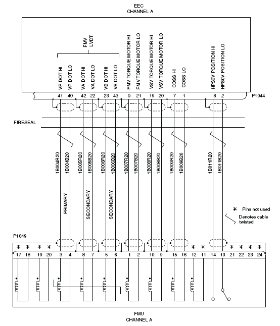
- Perform wiring checks between the EEC 1 CHA (P1044) to FMU1 (P1049)
- If wiring checks are not good, repair the defective wiring and do close out.
- If wiring checks are good, continue with next step.
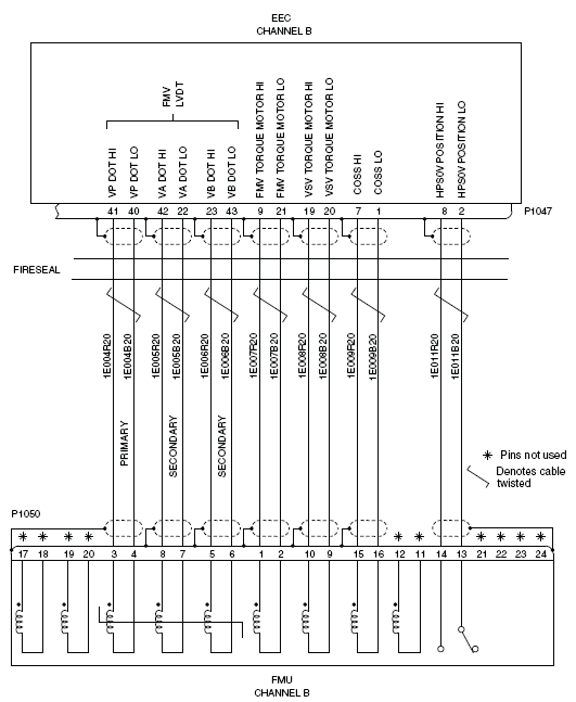
- Perform wiring checks between the EEC 1 CHB (P1047) to FMU1 (P1050)
- If wiring checks are not good, repair the defective wiring and do close out.
- If wiring checks are good, continue with next step.
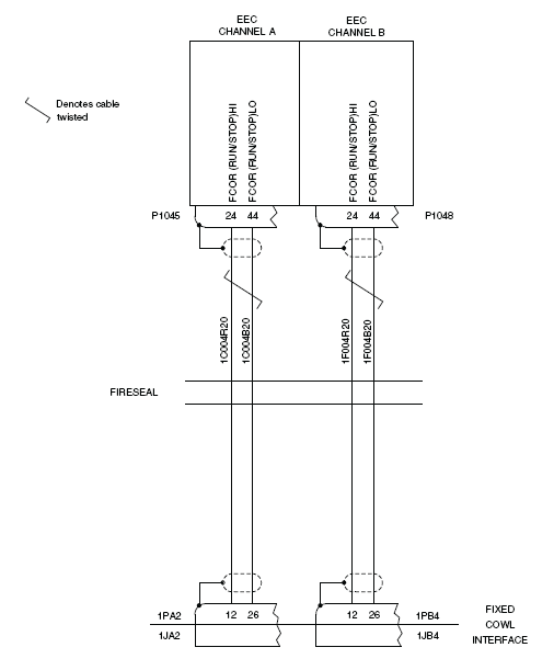
- Perform wiring checks between EEC 1 CHA (P1045) and EEC CHB (P1048) and the fixed cowl interface (2PA2 and 2PB4)
- If wiring checks are not good, repair the defective wiring and do close out.
- If wiring checks are good, continue with next step.
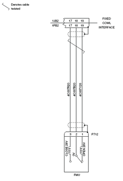
- Perform wiring checks between throttle quadrant (AP41P2) and FMU1 (P712)
- If wiring checks are not good, repair the defective wiring and do close out.
- If wiring checks are good, continue with next step.
- Perform wiring checks between throttle quadrant (AP41P2) and EEC1 CHA (P1045).
- If wiring checks are not good, repair the defective wiring and do close out.
- If wiring checks are good, continue with next step.
- Perform wiring checks between SPDA4 (A16P4) and throttle quadrant (AP41P2)
- If wiring checks are not good, repair the defective wiring and do close out.
- If wiring checks are good, continue with next step.
- Interchange SPDA 4 with SPDA
- If system checks are good, replace SPDA 4 and do close out.
- If fault remains, continue with next step.
- Replace throttle quadrant.
- If system checks are good, do close out.
- If fault remains, continue with next step.
- Replace FMU 1.
- Do close out.