

09/25/19
Message Overview:
Fault Message:
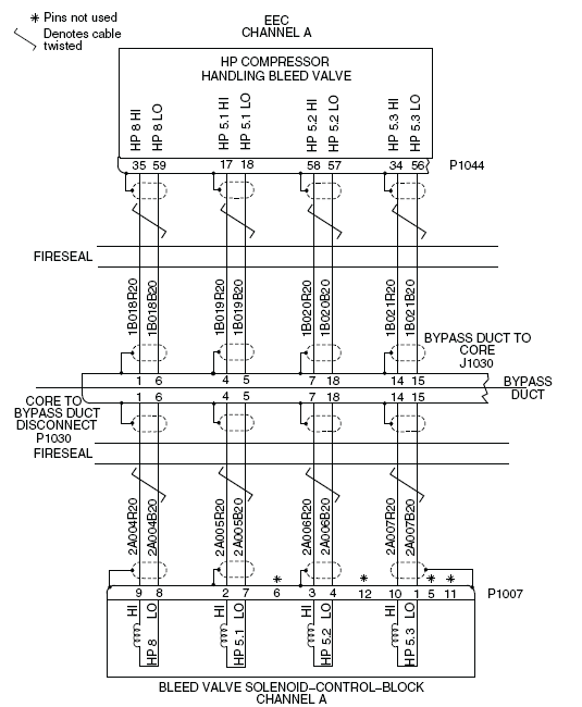
R BVSB 5.2 CH A WRG/BVSB RNG
Fault Code:
7325616RBR
Associated CAS:
| Reporting LRU: | Right Engine Electronic Controller (EEC) |
| System Description: | 75-30-00 |
| Schematic Diagram: | 75-31-00 [ Global Express ] [ G5000 ] [ Global XRS ] |
| Wiring Diagram: | 71-50-01 [ Global Express ] [ G5000 ] [ Global XRS ] 75-31-01 [ Global Express ] [ G5000 ] [ Global XRS ] |
Fault Description:
The fault message is set when:
- The resistance in Solenoid 5.2 (channel A) of the Bleed Valve Solenoid Control Block (BVSB) is not within limits
- There is an open or short circuit in the interface wiring
The BVSB circuits are checked during power-up and continuously monitored by the Full-Authority Digital Engine-Controller (FADEC).
Possible Causes:
- Right Engine Electronic Controller (EEC)
- Bleed Valve Solenoid Control Block (BVSB)
- Compressor Fairing
- Associated Wiring
Troubleshooting Tips:
Advisory Wire/Service Bulletin: None
Forum Articles/Infoservice/Newsletter: None
Quick Links:
| Engine Safety Precautions | AMM 71-00-00-910-801 [ Global Express ] [ G5000 ] [ Global XRS ] |
| Opening of the Cowls | AMM 71-10-00-010-801 [ Global Express ] [ G5000 ] [ Global XRS ] |
| Closing of the Cowls | AMM 71-10-00-410-801 [ Global Express ] [ G5000 ] [ Global XRS ] |
| Removal of the Bypass-Duct Access Panels (451AL/461AL, 451BL/461BL, 451CL/461CL, 451DL/461DL, 451EL/461EL, 452FR/462FR, 452GR/462GR, 452HR/462HR, 452JR/462JR, 452KR/462KR) |
AMM 72-71-01-000-801 [ Global Express ] [ G5000 ] [ Global XRS ] |
| Installation of the Bypass-Duct Access Panels (451AL/461AL, 451BL/461BL, 451CL/461CL, 451DL/461DL, 451EL/461EL, 452FR/462FR, 452GR/462GR, 452HR/462HR, 452JR/462JR, 452KR/462KR) |
AMM 72-71-01-400-801 [ Global Express ] [ G5000 ] [ Global XRS ] |
| Deactivation of the Thrust Reverser (for Maintenance) | AMM 78-30-00-040-801 [ Global Express ] [ G5000 ] [ Global XRS ] |
| Activation of the Thrust Reverser (for Maintenance) | AMM 78-30-00-440-801 [ Global Express ] [ G5000 ] [ Global XRS ] |
| Removal of the Compressor Fairings | EMM 72-03-01-000-801 [ Global Express ] [ G5000 ] [ Global XRS ] |
| Installation of the Compressor Fairings | EMM 72-03-01-400-801 [ Global Express ] [ G5000 ] [ Global XRS ] |
| Removal of the Engine Electronic Controller (EEC) | EMM 73-21-01-000-801 [ Global Express ] [ G5000 ] [ Global XRS ] |
| Installation of the Engine Electronic Controller (EEC) | EMM 73-21-01-400-801 [ Global Express ] [ G5000 ] [ Global XRS ] |
| Removal of the Bleed Valve Solenoid-Control-Block | EMM 75-31-02-000-801 [ Global Express ] [ G5000 ] [ Global XRS ] |
| Installation of the Bleed Valve Solenoid-Control-Block | EMM 75-31-02-400-801 [ Global Express ] [ G5000 ] [ Global XRS ] |
| Wire Repair - Maintenance Practices - ALL | SPM 20-12-10-02 [ Global Express ] [ G5000 ] [ Global XRS ] |
Troubleshooting Recommendations:
- Open the following circuit breakers:
- Perform a deactivation of the thrust reverser.
- Open the cowls.
- Remove the applicable bypass-duct access panel and the applicable compressor fairing.
- If the fault message is stored, fault could be intermittent.
- If the fault message is not stored, continue with next step.
- Disconnect the connector J1030 from the core lane A and disconnect P1030 on bypass duct.
- Perform a check of resistance of the BVSB as follows:
On A/C Post SB 75-101096From To Expected Result Result P1030-7 P1030-18 70 to 90 ohms at 68 °F (20 °C) ±1.70 ohms per 9 °F (5 °C) P1030-7 Ground >40 megohm On A/C Post SB 75-101161
From To Expected Result Result P1030-7 P1030-18 95 to 115 ohms at 68 °F (20 °C) ±1.70 ohms per 9 °F (5 °C) P1030-7 Ground >40 megohm - If the resistance values are not as specified above, repair defective wiring as required and go to step 17.
- If the resistance values are as specified above, continue with next step.
- Connect the connector J1030 to the core lane A and connect P1030.
- If the resistance values of the BVSB are not as specified, replace the BVSB and go to step 17.
- If the resistance values of the BVSB are as specified, continue with next step.
- Close the following circuit breakers:
- Connect the electrical power to the aircraft.
- If fault does not exist, go to step 14.
- If fault still exists, remove the electrical power from the aircraft and continue with next step.
- Open the following circuit breakers:
System Name Circuit Breaker Name Bus Name ENGINE R FADEC CH A BATT ENGINE R FADEC CH B BATT - If fault not exist, replace defective circuit breaker as required and go to step 17.
- If the fault message stays active or the resistance values are as specified, continue with next step.
- Perform wiring checks between the EEC connector P1044, bypass duct connector J1030 and the BVSB connector P1007.
- If wiring checks are not good, repair defective wiring as required and go to step 17.
- If wiring checks are good, continue with next step.
- Close the following circuit breakers:
System Name Circuit Breaker Name Bus Name ENGINE R FADEC CH A BATT ENGINE R FADEC CH B BATT - Connect the electrical power to the aircraft.
- Make sure that L (R) FADEC FAIL (caution) does not show on the EICAS display.
- If the L (R) FADEC FAIL (caution) message shows on the EICAS display, troubleshoot them first and continue with next step.
- If the L (R) FADEC FAIL (caution) message not show on the EICAS display, continue with next step.
- Remove the electrical power from the aircraft.
- Replace Right EEC.
- Close the cowls and activate Thrust Reverser.
- Do close out.
| System | Circuit Breaker Name | Bus Name |
|---|---|---|
| ENGINE | R FADEC CH A | BATT |
| ENGINE | R FADEC CH B | BATT |
| ENGINE | R ENG IGN 1 | BATT |
| ENGINE | R ENG IGN 2 | BATT |
| ENGINE | R ENG FUEL HPSOV | BATT |
| ENGINE | R ENG START A | BATT |
| ENGINE | R ENG START B | BATT |
| ENGINE | R T/R CTL VALVE | BATT |
| ENGINE | R T/R LOWER LOCK | BATT |
| ENGINE | R T/R UPPER LOCK | BATT |
| System Name | Circuit Breaker Name | Bus Name |
|---|---|---|
| ENGINE | R FADEC CH A | BATT |
| ENGINE | R FADEC CH B | BATT |