09/25/19
Message Overview:
Fault Message:
L DED GEN 3PH CH A WRG/DGEN RNG
Fault Code:
7325624LBR
Associated CAS:
| Reporting LRU: | Left Engine Electronic Controller (EEC) |
| System Description: | 73-20-00 |
| Schematic Diagram: | None |
| Wiring Diagram: | 71-50-01 [ Global Express ] [ G5000 ] [ Global XRS ] |
Fault Description:
An electrical fault has been detected with the Left Engine Dedicated Generator (DED GEN) 3 Phase to Engine Electronic Controller (EEC) CH A. Inhibited during Take-Off and Landing.
- There is an open or short circuit or resistance error in the 3-Phase windings of the Dedicated Generator Stator
- There is an open or short circuit in the interface wiring
Possible Causes:
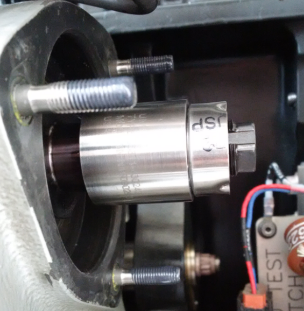
- Left Engine Dedicated Generator
- Dedicated Generator Stator
- Dedicated Generator Rotor
- Left Engine Electronic Controller (EEC)
- Associated Wiring
Troubleshooting Tips:
Advisory Wire/Service Bulletin:
- Service Bulletin (SB) BR700-73-101856 - Engine Fuel and Control - Dedicated Generator - Introduction of a new varnish for the windings of the Permanent Magnetic Alternator
Forum Articles/Infoservice/Newsletter:
- Forum - Volume 12, Issue 10 (May 19, 2015) - Rolls Royce Campaign to Replace Permanent Magnetic Alternator (PMA) Stators
NOTE: The dedicated generator circuits are monitored when the engine turns at more than 35% N2.
Quick Links:
| Opening of the Cowls | AMM 71-10-00-010-801 [ Global Express ] [ G5000 ] [ Global XRS ] |
| Closing of the Cowls | AMM 71-10-00-410-801 [ Global Express ] [ G5000 ] [ Global XRS ] |
| Deactivation of the Thrust Reverser (for Maintenance) | AMM 78-30-00-040-801 [ Global Express ] [ G5000 ] [ Global XRS ] |
| Activation of the Thrust Reverser (for Maintenance) | AMM 78-30-00-440-801 [ Global Express ] [ G5000 ] [ Global XRS ] |
| Operational Test of FADEC System | EMM 73-21-00-710-801 [ Global Express ] [ G5000 ] [ Global XRS ] |
| Removal of the Eng Electronic Controller (EEC) Mod 73-101559 |
EMM 73-21-01-000-801-B00 [ Global Express ] [ G5000 ] [ Global XRS ] |
| Installation of the Eng Electronic Controller (EEC) Mod 73-101559 |
EMM 73-21-01-400-801-B001 [ Global Express ] [ G5000 ] [ Global XRS ] |
| Removal of the Dedicated Generator | EMM 73-21-04-000-801 [ Global Express ] [ G5000 ] [ Global XRS ] |
| Installation of the Dedicated Generator | EMM 73-21-04-400-801 [ Global Express ] [ G5000 ] [ Global XRS ] |
| Wire Repair - Maintenance Practices - ALL | SPM 20-12-10-02 [ Global Express ] [ G5000 ] [ Global XRS ] |
Troubleshooting Recommendations:
- Perform a deactivation of the thrust reverser.
- Open the cowls.
- Perform wiring checks between the Left Engine Dedicated Generator (P1052) and the EEC 1 (P1043).
- If wiring checks are not good, repair defective wiring as required and go to step 10.
- If wiring checks are good, continue with next step.
- Perform the resistance checks for the Left dedicated generator stator as follow:
From To Maximum Resistance Allowed Result P1052-1 P1052-2 0.64 Ohms P1052-1 P1052-3 0.64 Ohms P1052-2 P1052-3 0.64 Ohms - If the resistance are not within range, go to step 8.
- If the resistance are within range, continue with next step.
- Perform an insulation check between the Left Engine Dedicated Generator (P1052) and the casing as follows:
From To Maximum Resistance Allowed Result P1052-1 Case >40 MΩ P1052-2 Case >40 MΩ P1052-3 Case >40 MΩ - If the insulation resistance is less than 40 MΩ, go to step 8.
- If the insulation resistance are within range, continue with next step.
- Examine the dedicated generator housing/stator for any sign of damage.
- If there is damage, replace the dedicated generator stator and go to step 10.
- If there is no damage, continue with next step.
- Examine the dedicated generator rotor for any sign of damage. Specifically look at heat discoloration and chaffing due to the stator damage.
- If there is damage, replace the dedicated generator rotor and go to step 10.
- If there is no damage, continue with next step.
- Replace the Left Dedicated Generator.
- If system checks are good, go to step 10.
- If fault remains, continue with next step.
- Replace the EEC 1.
- Close the cowls and activate thrust reverser.
- Do close out.
Example of Rotor Condition: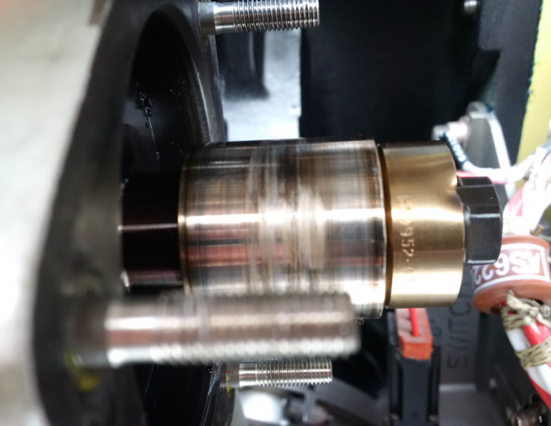
Damaged: Overheated and Fretting Sign