09/25/19
Message Overview:
Fault Message:
R ITT SIGNAL WRG XCK
Fault Code:
7325727RBR
Associated CAS:
| Reporting LRU: | Engine Electronic Controller (EEC) 2 |
| System Description: | 77-20-00 |
| Schematic Diagram: | 77-20-00 [ Global Express ] [ G5000 ] [ Global XRS ] |
| Wiring Diagram: | 71-50-01 [ Global Express ] [ G5000 ] [ Global XRS ] |
Fault Description:
There is an unsatisfactory difference between the signals from channel A and channel B of the Inter-Turbine Temperature (ITT) thermocouples. The ITT circuits are continuously monitored by the Full-Authority Digital Engine-Controller (FADEC).
Possible Causes:
- Inter-Turbine Temperature (ITT) Thermocouple
- Right Engine Electronic Controller (EEC)
- Associated Wiring
Troubleshooting Tips:
Advisory Wire/Service Bulletin: None
Forum Articles/Infoservice/Newsletter: None
Quick Links:
| Engine Safety Precautions | AMM 71-00-00-910-801 [ Global Express ] [ G5000 ] [ Global XRS ] |
| Opening of the Cowls | AMM 71-10-00-010-801 [ Global Express ] [ G5000 ] [ Global XRS ] |
| Closing of the Cowls | AMM 71-10-00-410-801 [ Global Express ] [ G5000 ] [ Global XRS ] |
| Removal of the Bypass-Duct Access Panels(451AL/461AL, 451BL/461BL, 451CL/461CL, 451DL/461DL,451EL/461EL, 452FR/462FR, 452GR/462GR, 452HR/462HR, 452JR/462JR, 452KR/462KR) |
AMM 72-71-01-000-801 [ Global Express ] [ G5000 ] [ Global XRS ] |
| Installation of the Bypass-Duct Access Panels(451AL/461AL, 451BL/461BL, 451CL/461CL, 451DL/461DL,451EL/461EL, 452FR/462FR, 452GR/462GR, 452HR/462HR,452JR/462JR, 452KR/462KR) |
AMM 72-71-01-400-801 [ Global Express ] [ G5000 ] [ Global XRS ] |
| Deactivation of the Thrust Reverser (for Maintenance) | AMM 78-30-00-040-801 [ Global Express ] [ G5000 ] [ Global XRS ] |
| Activation of the Thrust Reverser (for Maintenance) | AMM 78-30-00-440-801 [ Global Express ] [ G5000 ] [ Global XRS ] |
| Removal of the Combustion Section Fairings | EMM 73-03-02-000-801 [ Global Express ] [ G5000 ] [ Global XRS ] |
| Installation of the Combustion Section Fairings | EMM 73-03-02-400-801 [ Global Express ] [ G5000 ] [ Global XRS ] |
| Removal of the Engine Electronic Controller (EEC) | EMM 73-21-01-000-801 [ Global Express ] [ G5000 ] [ Global XRS ] |
| Installation of the Engine Electronic Controller (EEC) | EMM 73-21-01-400-801 [ Global Express ] [ G5000 ] [ Global XRS ] |
| Removal of the Inter-Turbine Temperature (ITT) Harness | EMM 77-21-02-000-801 [ Global Express ] [ G5000 ] [ Global XRS ] |
| Installation of the Inter-Turbine Temperature (ITT) Harness | EMM 77-21-02-400-801 [ Global Express ] [ G5000 ] [ Global XRS ] |
| Wire Repair - Maintenance Practices - ALL | SPM 20-12-10-02 [ Global Express ] [ G5000 ] [ Global XRS ] |
Troubleshooting Recommendations:
CAUTION: DO NOT DO ELECTRICAL CHECKS INTO THE ENGINE ELECTRONIC CONTROLLER (EEC). IF YOU DO NOT OBEY THIS INSTRUCTION, DAMAGE TO THE EEC CAN OCCUR.
- Open the circuit breakers that follow:
SYSTEM NAME CIRCUIT BREAKER NAME BUS NAME ENGINE R FADEC CH A BATT ENGINE R FADEC CH B BATT ENGINE R ENG IGN 1 BATT ENGINE R ENG IGN 2 BATT ENGINE R ENG FUEL HPSOV BATT ENGINE R ENG START A BATT ENGINE R ENG START B BATT ENGINE R T/R CTL VALVE BATT ENGINE R T/R LOWER LOCK BATT ENGINE R T/R UPPER LOCK BATT - Perform a deactivation of the thrust reverser.
- Open the cowls.
- Remove the applicable bypass-duct access panel and the applicable combustion section fairing.
- Examine the interface wiring for damage between the connectors and the terminal blocks that follow:
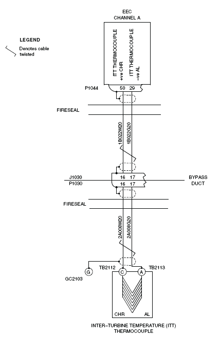
- The EEC connector P1044
- The bypass duct connectors J1030 and P1030
- The terminal blocks TB2112 and TB2113, and the ground connector GC2103
- The Alumel and Chromel connector posts on the ITT thermocouples
For Channel B:
For Channel A:
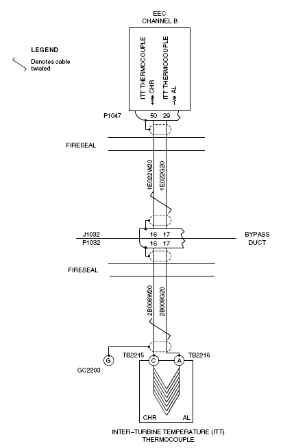
- The EEC connector P1047
- The bypass duct connectors J1032 and P1032
- The terminal blocks TB2215 and TB2216, and the ground connector GC2203
- The Alumel and Chromel connector posts on the ITT thermocouples
NOTE: Look specially for signs of damage adjacent to clip locations. - If there is a damage, repair or replace defective wiring as required and do close out.
- If there is no damage, continue with next step.
- Check if the fault message R ITT SIGNAL WRG XCK is active.
- If the fault message exists, replace the EEC 2 and do close out.
- If the fault message does not exists, continue with next step.
- Install the applicable combustion section fairing.
- Close the cowls.
- Perform the activation of the thrust reverser.
- Close the circuit breakers that follow:
SYSTEM NAME CIRCUIT BREAKER NAME BUS NAME ENGINE R FADEC CH A BATT ENGINE R FADEC CH B BATT ENGINE R ENG IGN 1 BATT ENGINE R ENG IGN 2 BATT ENGINE R ENG FUEL HPSOV BATT ENGINE R ENG START A BATT ENGINE R ENG START B BATT ENGINE R T/R CTL VALVE BATT ENGINE R T/R LOWER LOCK BATT ENGINE R T/R UPPER LOCK BATT - Connect the electrical power to the aircraft.
- Check if the fault message R ITT SIGNAL WRG XCK is active.
- If the fault message does not exists, go to step 26.
- If the fault message exists, continue with next step.
- Open the circuit breakers that follow:
SYSTEM NAME CIRCUIT BREAKER NAME BUS NAME ENGINE R FADEC CH A BATT ENGINE R FADEC CH B BATT ENGINE R ENG IGN 1 BATT ENGINE R ENG IGN 2 BATT ENGINE R ENG FUEL HPSOV BATT ENGINE R ENG START A BATT ENGINE R ENG START B BATT ENGINE R T/R CTL VALVE BATT ENGINE R T/R LOWER LOCK BATT ENGINE R T/R UPPER LOCK BATT - Perform a deactivation of the thrust reverser and open the cowls..
- Remove the applicable bypass-duct access panel and the applicable combustion section fairing.
- Disconnect the EEC connectors P1044 and P1047, and the bypass duct connectors P1030 and P1032.
- Disconnect the wiring at the terminal blocks TB2112, TB2113, TB2215 and TB2216, and at the ground connectors (GC2103 and GC2203).
- Examine the interface wiring and connectors for damage between the connectors and the terminal blocks that follow:
- The EEC connector P1044
- The bypass duct connectors J1030 and P1030
- The terminal blocks TB2112 and TB2113, and the ground connector GC2103
- The Alumel and Chromel connector posts on the ITT thermocouples
For channel B: - The EEC connector P1047
- The bypass duct connectors J1032 and P1032
- The terminal blocks TB2215 and TB2216, and the ground connector GC2203
- The Alumel and Chromel connector posts on the ITT thermocouples
NOTE: Look specially for signs of chafing adjacent to clip locations, condition of connector pins and wiring kink or strain.
For channel A:
- Perform wiring checks for channel A between TERMINAL BLOCK TB2112 and Bypass Duct (P1030).
- If wiring checks are not good, repair defective wiring as required and do close out.
- If wiring checks are good, continue with next step.
- Perform wiring checks for channel A between TERMINAL BLOCK TB2113 and Bypass Duct (P1030).
- If wiring checks are not good, repair defective wiring as required and do close out.
- If wiring checks are good, continue with next step.
- Perform wiring checks for channel A between Bypass Duct (J1030) and EEC (P1044).
- If wiring checks are not good, repair defective wiring as required and do close out.
- If wiring checks are good, continue with next step.
- Perform wiring checks for channel B between TERMINAL BLOCK TB2215 and Bypass Duct (P1032).
- If wiring checks are not good, repair defective wiring as required and do close out.
- If wiring checks are good, continue with next step.
- Perform wiring checks for channel B between TERMINAL BLOCK TB2216 and Bypass Duct (P1032).
- If wiring checks are not good, repair defective wiring as required and do close out.
- If wiring checks are good, continue with next step.
- Perform wiring checks for channel B between Bypass Duct (J1032) and EEC (P1047).
- If wiring checks are not good, repair defective wiring as required and do close out.
- If wiring checks are good, continue with next step.
- Install the applicable combustion section fairing and the applicable bypass-duct access panel.
- Close the cowls.
- Perform the activation of the thrust reverser.
- Close the circuit breakers that follow:
SYSTEM NAME CIRCUIT BREAKER NAME BUS NAME ENGINE RFADEC CH A BATT ENGINE R FADEC CH B BATT ENGINE R ENG IGN 1 BATT ENGINE R ENG IGN 2 BATT ENGINE R ENG FUEL HPSOV BATT ENGINE R ENG START A BATT ENGINE R ENG START B BATT ENGINE R T/R CTL VALVE BATT ENGINE R T/R LOWER LOCK BATT ENGINE R T/R UPPER LOCK BATT - Connect the electrical power to the aircraft.
- Check if the fault message R ITT SIGNAL WRG XCK is active.
- If the fault message exists, replace the ITT harness.
- If the fault message does not exists, continue with next step.
- Check if the fault message R ITT SIGNAL WRG XCK is active.
- If the fault message exists, replace the ITT thermocouple(s)
- If the fault message does not exists, continue with next step.
- Make sure that the primary indication of ITT shows on the EICAS display.
- Disconnect the electrical power to the aircraft.
- Do close out.