10/19/22
Message Overview:
Message Name:
L FMU [HPSOV]
Message Code:
7326320LBR
Associated CAS:
| Reporting LRU: | Left Engine Electronic Controller (EEC) |
| System Description: | 73-20-00 |
| Schematic Diagram: | None |
| Wiring Diagram: | 71-50-01 [ Global Express ] [ G5000 ] [ Global XRS ] |
Message Description:
The High Pressure Shut-off Valve (HPSOV) in the Fuel Metering Unit (FMU) does not open or close correctly. This problem shows when the ENGINE RUN switch position (on the throttle quadrant) does not agree with the HPSOV microswitches for channel A and B. The FMU circuits are continuously monitored by the Full-Authority Digital Engine-Controller (FADEC).
Possible Causes:
- SPDA 4 (A16)
- Fuel Metering Unit (FMU)
- Left Engine Electronic Controller (EEC)
- Low Pressure (LP) Fuel Pump
- Associated Wiring
Troubleshooting Tips:
Advisory Wire/Service Bulletin:
- AW700-45-0065 - CAIMS Nuisance Fault Messages
Forum Articles/Infoservice/Newsletter: None
Notice To Operators (NTO):
- Rolls-Royce NTO 175 - Nuisance Cockpit Effects and Fault Messages
Flight Operation Notifications Manual (FONM): None
NOTE: If the message CAIMS - L EEC [DUAL LANE HEALTH] also shows, do not perform this procedure, but perform the steps that follow:
- Remove the EEC (EMM TASK 73-21-01-000-801)
- Install a new EEC (EMM TASK 73-21-01-400-801)
NOTE: A failure of the LP Fuel pump and/or splined coupling could cause a loss of pressure and subsequent loss of HPSOV control. This scenario would trigger this fault code.
Quick Links:
| Engine Safety Precautions | AMM 71-00-00-910-801 [ Global Express ] [ G5000 ] [ Global XRS ] |
| Wet Motor the Engine | AMM 71-00-00-866-805 [ Global Express ] [ G5000 ] [ Global XRS ] |
| Opening of the Cowls | AMM 71-10-00-010-801 [ Global Express ] [ G5000 ] [ Global XRS ] |
| Closing of the Cowls | AMM 71-10-00-410-801 [ Global Express ] [ G5000 ] [ Global XRS ] |
| Deactivation of the Thrust Reverser (for Maintenance) | AMM 78-30-00-040-801 [ Global Express ] [ G5000 ] [ Global XRS ] |
| Activation of the Thrust Reverser (for Maintenance) | AMM 78-30-00-440-801 [ Global Express ] [ G5000 ] [ Global XRS ] |
| Removal of the Eng Electronic Controller (EEC) Mod 73-101559 |
EMM 73-21-01-000-801-B00 [ Global Express ] [ G5000 ] [ Global XRS ] |
| Installation of the Eng Electronic Controller (EEC) Mod 73-101559 |
EMM 73-21-01-400-801-B001 [ Global Express ] [ G5000 ] [ Global XRS ] |
| Removal of the Fuel Metering Unit (FMU) | EMM 73-21-03-000-801 [ Global Express ] [ G5000 ] [ Global XRS ] |
| Installation of the Fuel Metering Unit (FMU) | EMM 73-21-03-400-801 [ Global Express ] [ G5000 ] [ Global XRS ] |
| Wire Repair - Maintenance Practices - ALL | SPM 20-12-10-02 [ Global Express ] [ G5000 ] [ Global XRS ] |
Troubleshooting Recommendations:
CAUTION: DO NOT PERFORM ELECTRICAL CHECKS INTO THE ENGINE ELECTRONIC CONTROLLER (EEC). IF YOU DO NOT OBEY THIS INSTRUCTION, DAMAGE TO THE EEC CAN OCCUR.
- Perform the fault/repair confirmation. Perform the operational test of the FADEC.
NOTE: Repeat the fault/repair confirmation after every unit replacement/repair. Two subsequent engine starts/shutdowns are required to clear this fault. If no fault message is active, then you corrected the fault. Exit troubleshooting.- If fault remains, troubleshoot them first and continue with next step.
- If the system checks are good, continue with next step.
- Using CAIMS, get access to the fault messages.
- If the fault message does not show, then there was an intermittent fault.
- If the L FMU [HPSOV] FAIL fault messages is active or in the fault history, continue with next step.
- Check when is the fault message set?
- If the fault message was set during engine shutdown, continue with the next step.
- Open the cowl doors.
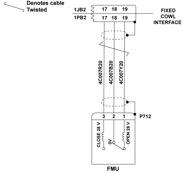
- Disconnect the connectors P712 and 1PB2.
- Perform a visual inspection of FMU receptacle (U712).
- If damage is found, go to step 12.
- If damage is not found, continue with next step.
- Perform a visual inspection of FMU connectors (P712) and Fixed cowl connectors (1PB2).
NOTE: Look specially for signs of chafing adjacent to clip locations, the condition of connector pins and for kinks and strains in the wiring.- If damage is found, repair or replace the harness as required and go to step 15.
- If damage is not found, continue with next step.
- Set the engine FCS to "OFF". Measure for 28 VDC at connector P712 as follows:
From To Result P712-2 P712-3 - If there is 28 VDC, go to step 12.
- If there is no 28 VDC, continue with next step.
- Interchange SPDA 4 and SPDA 1.
- If system checks are good, replace SPDA 4 and go to step 15.
- If fault remains, continue with next step.
- Perform continuity check between the connectors of Fixed Cowl Interface and FMU as follows:
From To Result 1PB2-17 P712-3 1PB2-18 P712-2 1PB2-19 P712-1 - If there is no continuity, repair defective wiring as required and go to step 15.
- If there is continuity, continue with next step.
- Perform a check of the insulation resistance of the interface between the Fixed Cowl and the FMU as follows:
From To Expected Result Result P712-3 Ground 20 ΜΩ or more P712-2 Ground 20 ΜΩ or more P712-1 Ground 20 ΜΩ or more - If there is no continuity or insulation resistance is not as specified, repair or replace the harness as required and go to step 15.
- If there is continuity or insulation resistance is as specified, continue with next step.
- Replace the FMU.
- If system checks are good, go to step 15.
- If fault remains, continue with next step.
- Replace the EEC.
- If system checks are good, go to step 15.
- If fault remains, continue with next step.
- Replace the TQA (FCS).
- Close the cowl doors.
- Do close out.