10/01/19
Message Overview:
Fault Message:
R T20 PROBE RNG MA
Fault Code:
7327025RBR
Associated CAS:
| Reporting LRU: | Right Engine Electronic Controller (EEC) |
| System Description: | 73-20-00 |
| Schematic Diagram: | None |
| Wiring Diagram: | 71-50-01 [ Global Express ] [ G5000 ] [ Global XRS ] |
Fault Description:
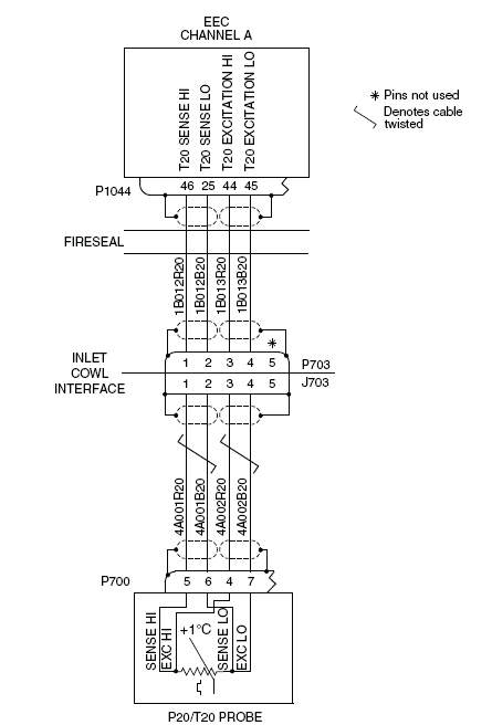
This message shows when there is an open circuit or a short circuit in the P20/T20 Probe or the related wiring. The P20/T20 Probe circuits are continuously monitored by the Full-Authority Digital Engine-Controller (FADEC).
Possible Causes:
- P20/T20 Probe
- Right Engine Electronic Controller (EEC)
- Associated Wiring
Troubleshooting Tips:
Advisory Wire/Service Bulletin:
- AW700-45-0065 - CAIMS Nuisance Fault Messages
Forum Articles/Infoservice/Newsletter: None
Quick Links:
| Engine Safety Precautions | AMM 71-00-00-910-801 [ Global Express ] [ G5000 ] [ Global XRS ] |
| Opening of the Cowls | AMM 71-10-00-010-801 [ Global Express ] [ G5000 ] [ Global XRS ] |
| Closing of the Cowls | AMM 71-10-00-410-801 [ Global Express ] [ G5000 ] [ Global XRS ] |
| Deactivation of the Thrust Reverser (for Maintenance) | AMM 78-30-00-040-801 [ Global Express ] [ G5000 ] [ Global XRS ] |
| Activation of the Thrust Reverser (for Maintenance) | AMM 78-30-00-440-801 [ Global Express ] [ G5000 ] [ Global XRS ] |
| Removal of the P20/T20 Access Panel | EMM 54-10-01-000-803 [ Global Express ] [ G5000 ] [ Global XRS ] |
| Installation of the P20/T20 Access Panel | EMM 54-10-01-400-803 [ Global Express ] [ G5000 ] [ Global XRS ] |
| Connection of Electrical Connectors | EMM 70-50-01-910-801 [ Global Express ] [ G5000 ] [ Global XRS ] |
| Removal of the P20/T20 Probe | EMM 73-21-05-000-801 [ Global Express ] [ G5000 ] [ Global XRS ] |
| Installation of the P20/T20 Probe | EMM 73-21-05-400-801 [ Global Express ] [ G5000 ] [ Global XRS ] |
| Cleaning of the P20/T20 Probe | EMM 73-21-05-XXX-XXX TV172998 [ Global Express ] [ G5000 ] [ Global XRS ] |
| Operational Test of the P20/T20 Probe | EMM 73-21-05-710-801 [ Global Express ] [ G5000 ] [ Global XRS ] |
| Wire Repair - Maintenance Practices - ALL | SPM 20-12-10-02 [ Global Express ] [ G5000 ] [ Global XRS ] |
Troubleshooting Recommendations:
CAUTION: DO NOT DO ELECTRICAL CHECKS INTO THE ENGINE ELECTRONIC CONTROLLER (EEC). IF YOU DO NOT OBEY THIS INSTRUCTION, DAMAGE TO THE EEC CAN OCCUR.
- Remove the electrical power from the aircraft and open the following circuit breakers:
System Name Circuit Breaker Name Bus Name ENGINE R ENG FUEL HPSOV BATT BATT ENGINE R ENG IGN 1 BATT ENGINE R ENG IGN 2 BATT BATT ENGINE R FADEC CH A BATT BATT ENGINE R FADEC CH B BATT BATT ENGINE R ENG START A BATT BATT ENGINE R ENG START B BATT BATT - Open and tag the circuit breaker.
Location CB No. Name Zone CCBP F9 TAT HT 2 222 - Perform a deactivation of the thrust reverser.
- Open the cowls.
- Remove the access panel (441AT).
- Perform wiring checks between P20/T20 PROBE (P700) and INLET COWL INTERFACE (J703).
- If wiring checks are not good, repair defective wiring as required and go to step 10.
- If wiring checks are good, continue with next step.
- Perform wiring checks between INLET COWL INTERFACE (P703) and EEC (P1044).
- If wiring checks are not good, repair defective wiring as required and do go to step 10.
- If wiring checks are good, continue with next step.
- Clean the P20/T20 probe. Is the fault still present?
- If NO, go to step 10.
- If YES, continue with next step.
- Replace the P20/T20 probe.
- Install the access panel (441AT).
- Close the cowls and perform a activation of the thrust reverser.
- Do close out.