07/21/25
Message Overview:
Message Name:
R ITT CH B WRG/PROBE RNG MA
Message Code:
7327229RBR
Associated CAS:
EEC software C6 & C7
EEC software C8 & X
| Reporting LRU: | Engine Electronic Controller (EEC) 2 |
| System Description: | 77-20-00 - Temperature |
| Schematic Diagram: | [ Global Express ] [ G5000 ] [ Global XRS ] SMM 77-20-00-101 - Engine Temperature Indicating System - Electrical Schematic |
| Wiring Diagram: | [ Global Express ] [ G5000 ] [ Global XRS ] WM 71-50-00-01 - Engine Electrical Harness [ Global Express ] [ G5000 ] [ Global XRS ] WM 77-20-00-01 - Engine Temperature Indicating System |
Message Description:
There is an open or short circuit in the interface wiring. The Inter-Turbine Temperature (ITT) circuits are continuously monitored by the Full-Authority Digital Engine-Controller (FADEC).
Possible Causes:
- Inter-Turbine Temperature (ITT) Thermocouples
- Right Engine Electronic Controller (EEC)
- Associated Wiring
Troubleshooting Tips:
Advisory Wire/Service Bulletin: None
Full Throttle Blog/Forum Articles/Infoservice/Newsletter: None
Flight Operation Notifications Manual (FONM): None
NOTES:
- If lost of ITT indication on the EICAS display due to the CHA and/or CHB failure; Dashes will appear instead of the indication.
Quick Links:
| Connect Electrical Power to the Aircraft | [ G5000 ] [ Global Express ] [ Global XRS ] AMM24-00-00-861-801 |
| Remove the Electrical Power from the Aircraft | [ G5000 ] [ Global Express ] [ Global XRS ] AMM24-00-00-861-802 |
| Access to Active Faults | [ G5000 ] [ Global Express ] [ Global XRS ] AMM45-45-00-970-802 |
| Access to Stored Faults | [ G5000 ] [ Global Express ] [ Global XRS ] AMM45-45-00-970-803 |
| Standard Aircraft Configuration for Maintenance | [ G5000 ] [ Global Express ] [ Global XRS ] AMM12-00-00-867-801 |
| Aircraft Walkaround (for Maintenance) | [ G5000 ] [ Global Express ] [ Global XRS ] AMM12-00-00-867-802 |
| Connect Electrical Power to the Aircraft | [ G5000 ] [ Global Express ] [ Global XRS ] AMM24-00-00-861-801 |
| Remove the Electrical Power from the Aircraft | [ G5000 ] [ Global Express ] [ Global XRS ] AMM24-00-00-861-802 |
| Opening of Non-Thermal Circuit Breakers | [ G5000 ] [ Global Express ] [ Global XRS ] AMM24-00-00-863-801 |
| Closing of Non-Thermal Circuit Breakers | [ G5000 ] [ Global Express ] [ Global XRS ] AMM24-00-00-863-802 |
| Electrostatic Discharge Safety Precautions | [ G5000 ] [ Global Express ] [ Global XRS ] AMM24-00-00-910-802 |
| Engine Safety Precautions | [ G5000 ] [ Global Express ] [ Global XRS ] AMM71-00-00-910-801 |
| Opening of the Cowls (432AB/442AB, 432AT/442AT) | [ G5000 ] [ Global Express ] [ Global XRS ] AMM71-10-00-010-801 |
| Closing of the Cowls (432AB/442AB, 432AT/442AT) | [ G5000 ] [ Global Express ] [ Global XRS ] AMM71-10-00-410-801 |
| Removal of the Bypass-Duct Access Panels (451AL/461AL, 451BL/461BL, 451CL/461CL, 451DL/461DL, 451EL/461EL, 452FR/462FR, 452GR/462GR, 452HR/462HR, 452JR/462JR, 452KR/462KR) | [ G5000 ] [ Global Express ] [ Global XRS ] AMM72-71-01-000-801 |
| Installation of the Bypass-Duct Access Panels (451AL/461AL, 451BL/461BL, 451CL/461CL, 451DL/461DL, 451EL/461EL, 452FR/462FR, 452GR/462GR, 452HR/462HR, 452JR/462JR, 452KR/462KR) | [ G5000 ] [ Global Express ] [ Global XRS ] AMM72-71-01-400-801 |
| Deactivation of the Thrust Reverser (for Maintenance) | [ G5000 ] [ Global Express ] [ Global XRS ] AMM78-30-00-040-801 |
| Reactivation of the Thrust Reverser (for Maintenance) | [ G5000 ] [ Global Express ] [ Global XRS ] AMM78-30-00-440-801 |
| Standard Aircraft Configuration for Maintenance | [ G5000 ] [ Global Express ] [ Global XRS ] AMM12-00-00-867-801 |
| Aircraft Walkaround (for Maintenance) | [ G5000 ] [ Global Express ] [ Global XRS ] AMM12-00-00-867-802 |
Troubleshooting Recommendations:
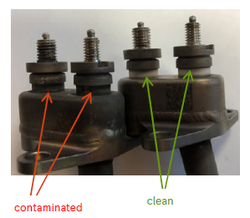
- Perform a visual inspection of the ITT Thermocouple.
NOTE: Look specially for signs of damage adjacent to clip locations and corrosion around the ceramic insulator.- If damage or defect are found, repair as required and do close out.
- If damage or defect are not found, continue with next step.
- Interchange EECs.
- If system checks are good, replace the defective EEC and do close out.
- If fault remains continue with the next step.
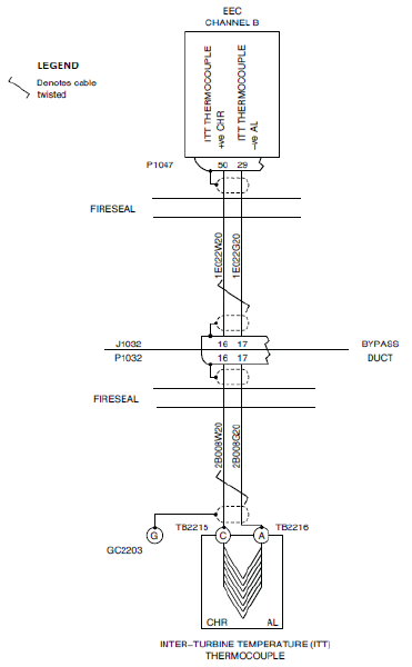
- Disconnect the EEC connector P1047 and the bypass duct connector P1032 and J1032. Disconnect the interface wiring at the terminal blocks TB2215 and TB2216, and the ground connector GC2203. Perform a visual inspection of the associated wiring and connectors for damage between the connectors and the terminal blocks.
NOTE: Look specially for signs of chafing adjacent to clip locations, condition of connector pins and wiring kink or strain.- If defects are found, repair as required and do close out.
- If defects are not found, continue with next step.
- Perform a continuity check between the terminal blocks TB2215 and TB2216 (Alumel and Chromel terminal lugs) and the connector P1032 that follows:
From To Result TB2215 P1032-16 TB2216 P1032-17 - If there is no continuity, repair defective wiring as required and do close out.
- If there is continuity, continue with the next step.
- Perform a continuity check between the connectors J1032 and P1047 that follows:
From To Result J1032-16 P1047-50 J1032-17 P1047-29 - If there is no continuity, repair defective wiring as required and do close out.
- If there is continuity, continue with the next step.
- Disconnect Thermocouple (Ladder) Harness from the Thermocouples.
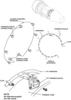
- Do wiring check of Thermocouple (Ladder) Harness for continuity.
- If Harness has continuity between all connection points replace the defective TGT Thermocouple.
- If Thermocouple Harness does not have continuity between connection points replace Thermocouple Harness.
- Make sure that the primary indication of ITT shows on the EICAS display.
- Do close out.