11/30/21
Message Overview:
Message Name:
L N1 SPEED WRG/PROBE SHARED RNG MA
Message Code:
7327326LBR
Associated CAS:
| Reporting LRU: | Left Engine Electronic Controller (EEC) |
| System Description: | 73-20-00 |
| Schematic Diagram: | None |
| Wiring Diagram: | [ Global Express ] [ G5000 ] [ Global XRS ] 71-50-01- Sheet 7 - By Pass (Lane B) and Thrust Reversers - ALL |
Messge Description:
The fault message is set when the Engine Electronic Controller (EEC) senses that the signal from the N1 Speed Probe shared is out-of-limits. During engine operation the Speed Probe circuits are continuously monitored by the Full-Authority Digital Engine-Controller (FADEC).
Possible Causes:
- N1 Speed Probe
- Left Engine Electronic Controller (EEC)
- Associated Wiring
Troubleshooting Tips:
Advisory Wire/Service Bulletin: None
Forum Articles/Infoservice/Newsletter: None
Quick Links:
| Engine Safety Precautions | AMM 71-00-00-910-801 [ Global Express ] [ G5000 ] [ Global XRS ] |
| Opening of the Cowls | AMM 71-10-00-010-801 [ Global Express ] [ G5000 ] [ Global XRS ] |
| Closing of the Cowls | AMM 71-10-00-410-801 [ Global Express ] [ G5000 ] [ Global XRS ] |
| Deactivation of the Thrust Reverser (for Maintenance) | AMM 78-30-00-040-801 [ Global Express ] [ G5000 ] [ Global XRS ] |
| Activation of the Thrust Reverser (for Maintenance) | AMM 78-30-00-440-801 [ Global Express ] [ G5000 ] [ Global XRS ] |
| Removal of the Engine Electronic Controller (EEC) | EMM 73-21-01-000-801-B00 [ Global Express ] [ G5000 ] [ Global XRS ] |
| Installation of the Engine Electronic Controller (EEC) | EMM 73-21-01-400-801-B001 [ Global Express ] [ G5000 ] [ Global XRS ] |
| Wire Repair - Maintenance Practices - ALL | SPM 20-12-10-02 [ Global Express ] [ G5000 ] [ Global XRS ] |
Troubleshooting Recommendations:
WARNING: BE CAREFUL WHEN YOU DO WORK ON THE ENGINE DURING OR AFTER AN ENGINE OPERATION. THE ENGINE PARTS STAY HOT FOR APPROXIMATELY THREE HOURS AFTER THE ENGINE STOPS. THIS CAN CAUSE INJURY TO PERSONS.
WARNING: BE CAREFUL IF YOU MUST DO WORK ON HOT COMPONENTS. USE APPROVED GLOVES AND PROTECTIVE CLOTHING. IF YOU DO NOT DO THIS, YOU CAN CAUSE INJURY TO PERSONS.
- Check if the fault message is stored.
- If NO, do close out.
- If YES, the fault could be intermittent so continue with next step.
- Perform the fault isolation for the N1 speed probe. In the flight compartment, on the EMS CDU, open the circuit breakers that follow:
System Name Circuit Breaker Name Bus Name ENGINE L ENG FUEL HPSOV BATT ENGINE L ENG IGN 1 BATT ENGINE L ENG IGN 2 BATT ENGINE L ENG START A BATT ENGINE L ENG START B BATT ENGINE L FADEC CH A BATT ENGINE L FADEC CH B BATT - Perform a deactivation of the thrust reverser and open the cowls.
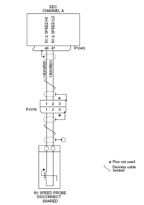
- Perform a visual inspection of the interface wiring, for damage between the EEC connector P1043 and N1 speed probe connector P1076.
NOTE: Look specially for signs of damage adjacent to clip locations.- If there is damage, repair as required and go to step 15.
- If there is no damage, continue with next step.
- Monitor the system to see if the fault message occurs again.
- If the fault message is not active, go to step 15.
- If the fault message is active, continue with next step.
- In the flight compartment, on the EMS CDU, open the circuit breakers that follow:
System Name Circuit Name Bus Name ENGINE L ENG FUEL HPSOV BATT ENGINE L ENG IGN 1 BATT ENGINE L ENG IGN 2 BATT ENGINE L ENG START A BATT ENGINE L ENG START B BATT ENGINE L FADEC CH A BATT ENGINE L FADEC CH B BATT - Disconnect the EEC connector P1043 and the N1 speed probe shared connector P1076. Perform a visual inspection of the interface wiring and connectors for damage between EEC connector P1043 and N1 speed probe shared connector P1076.
CAUTION: DO NOT DO ELECTRICAL CHECKS INTO THE ENGINE ELECTRONIC CONTROLLER (EEC). IF YOU DO NOT OBEY THIS INSTRUCTION, DAMAGE TO THE EEC CAN OCCUR.
NOTE: Look specially for signs of chafing adjacent to clip locations, condition of connector pins and wiring kink or strain.- If there is damage, repair as required and go to step 15.
- If there is no damage, continue with next step.
- Perform wiring checks between N1 Speed Probe Shared (P1076) and EEC (P1043).
- If wiring checks are not good, repair defective wiring as required and go to step 15.
- If wiring checks are good, continue with next step.
- Perform a check of the insulation resistance of the interface between the EEC and the N1 speed probe as follows:
From To Expected Result Result P1046-45 Ground ≥20 megohm P1046-25 Ground ≥20 megohm - If insulation resistance is not as specified, repair defective wiring as required and go to step 15.
- If insulation resistance is as specified, continue with next step.
- Connect the EEC connector P1043 and the N1 speed probe shared connector P1076.
- Check if the fault message is active.
- If the fault message stays active, the N1 speed probe shared or its attached core interface wiring are defective. This can only be repaired when the engine has an overhaul. Continue the fault isolation at the next engine overhaul.
- If the fault message is not active, go to step 15.
- Connect electrical power to the aircraft.
- Make sure that EICAS L FADEC FAIL (caution) does not show on the EICAS display.
- Remove the electrical power from the aircraft.
- Close the cowls and activate the thrust reverser.
- Do close out.