10/01/19
Message Overview:
Fault Message:
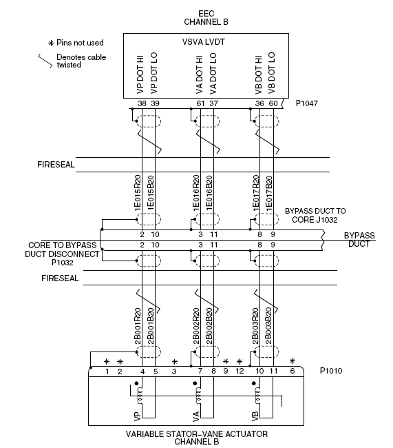
R VSVA CH B WRG/VSVA[LVDT] RNG
Fault Code:
7327421RBR
Associated CAS:
| Reporting LRU: | Right Engine Electronic Controller (EEC) |
| System Description: | 75-30-00 |
| Schematic Diagram: | 75-31-00 [ Global Express ] [ G5000 ] [ Global XRS ] |
| Wiring Diagram: | 71-50-01 [ Global Express ] [ G5000 ] [ Global XRS ] 75-31-01 [ Global Express ] [ G5000 ] [ Global XRS ] |
Fault Description:
There is an error of resistance or an open or short circuit in the Linear-Variable Differential Transformer (LVDT) of the Variable Stator-Vane Actuator (VSVA) for the Engine Electronic Controller (EEC) 2 channel B. Inhibited during Take-off and Landing.
Possible Causes:
- Variable Stator-Vane Actuator (VSVA)
- Right Engine Electronic Controller (EEC)
- Associated Wiring
Troubleshooting Tips:
Advisory Wire/Service Bulletin: None
Forum Articles/Infoservice/Newsletter: None
NOTE: The VSVA circuits are continuously monitored during engine operation and during power-up of the FADEC.
Quick Links:
| Opening of the Cowls | AMM 71-10-00-010-801 [ Global Express ] [ G5000 ] [ Global XRS ] |
| Closing of the Cowls | AMM 71-10-00-410-801 [ Global Express ] [ G5000 ] [ Global XRS ] |
| Removal of the Bypass-Duct Access Panels (451AL/461AL, 451BL/461BL, 451CL/461CL, 451DL/461DL,451EL/461EL, 452FR/462FR, 452GR/462GR, 452HR/462HR,452JR/462JR, 452KR/462KR) |
AMM 72-71-01-000-801 [ Global Express ] [ G5000 ] [ Global XRS ] |
| Installation of the Bypass-Duct Access Panels (451AL/461AL, 451BL/461BL, 451CL/461CL, 451DL/461DL,451EL/461EL, 452FR/462FR, 452GR/462GR, 452HR/462HR,452JR/462JR, 452KR/462KR) |
AMM 72-71-01-400-801 [ Global Express ] [ G5000 ] [ Global XRS ] |
| Deactivation of the Thrust Reverser (for Maintenance) | AMM 78-30-00-040-801 [ Global Express ] [ G5000 ] [ Global XRS ] |
| Activation of the Thrust Reverser (for Maintenance) | AMM 78-30-00-440-801 [ Global Express ] [ G5000 ] [ Global XRS ] |
| Removal of the Compressor Fairings | EMM 72-03-01-000-801 [ Global Express ] [ G5000 ] [ Global XRS ] |
| Installation of the Compressor Fairings | EMM 72-03-01-400-801 [ Global Express ] [ G5000 ] [ Global XRS ] |
| Removal of the Engine Electronic Controller (EEC) | EMM 73-21-01-000-801 [ Global Express ] [ G5000 ] [ Global XRS ] |
| Installation of the Engine Electronic Controller (EEC) | EMM 73-21-01-400-801 [ Global Express ] [ G5000 ] [ Global XRS ] |
| Removal of the Variable Stator-Vane Actuator | EMM 75-31-01-000-801 [ Global Express ] [ G5000 ] [ Global XRS ] |
| Installation of the Variable Stator-Vane Actuator | EMM 75-31-01-400-801 [ Global Express ] [ G5000 ] [ Global XRS ] |
| Wire Repair - Maintenance Practices - ALL | SPM 20-12-10-02 [ Global Express ] [ G5000 ] [ Global XRS ] |
Troubleshooting Recommendations:
CAUTION: Do not do electrical checks into the Engine Electronic Controller (EEC). If you do not obey this instruction, damage to the EEC can occur.
- Perform a deactivation of the thrust reverser.
- Open the cowls.
- Remove the applicable bypass-duct access panel and the applicable compressor fairing.
- Perform wiring check between the EEC 2 connector (P1047), the bypass duct connector (J1032) and the VSVA connector (P1010).
- If wiring checks are not good, repair defective wiring as required and go to step 7.
- If wiring checks are good, continue with next step.
- Swap the Right EEC with Left EEC. Is the fault still present.
- If NO, replace Right EEC and go to step 7.
- If YES, continue with next step.
- Replace VSVA.
- Close the cowls.
- Perform a activation of the thrust reverser.
- Do close out.