10/07/19
Message Overview:
Fault Message:
R CH B LOW TENSION IGNITION[2] RNG
Fault Code:
7326219RBR
Associated CAS:
| Reporting LRU: | Right Engine Electronic Controller (EEC) |
| System Description: | 74-20-00 |
| Schematic Diagram: | None |
| Wiring Diagram: | 71-50-01 [ Global Express ] [ G5000 ] [ Global XRS ] 74-00-01 [ Global Express ] [ G5000 ] [ Global XRS ] |
Fault Description:
WARNING: BEFORE YOU TOUCH THE IGNITION SYSTEM COMPONENTS, MAKE SURE OF THE CONDITIONS THAT FOLLOW:
- ISOLATE THE POWER SUPPLY (MAKE SURE THE APPLICABLE CIRCUIT BREAKERS ARE OPEN)
- AFTER YOU ISOLATE THE POWER SUPPLY, DO NOT TOUCH THE IGNITION SYSTEM COMPONENTS BEFORE A MINIMUM OF THREE MINUTES
YOU MUST DO THIS TO MAKE SURE THE RESIDUAL CURRENT DECREASES TO A SAFE LEVEL. THE IGNITION SYSTEM HAS VERY HIGH VOLTAGES WHICH CAN KILL YOU.
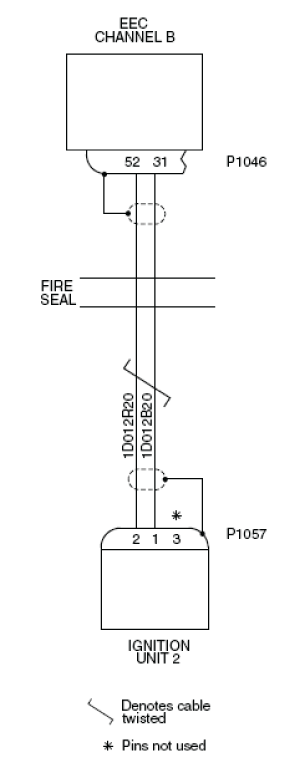
The fault message is set when there is an open or short circuit in the low-tension circuit of Ignition System 2. The fault is found between the Engine Electronic Controller (EEC) and the Ignition Unit 2. The low-tension ignition circuits are continuously monitored by the Full-Authority Digital Engine-Controller (FADEC).
Possible Causes:
- Ignition Unit 2
- Right Engine Electronic Controller (EEC)
- Associated Wiring
Troubleshooting Tips:
Advisory Wire/Service Bulletin:
- Rolls-Royce NTO 244 - Ignition System Logic and Improved Troubleshooting Sequence for Ignition System related Starting Issues
Forum Articles/Infoservice/Newsletter: None
Quick Links:
| Engine Safety Precautions | AMM 71-00-00-910-801 [ Global Express ] [ G5000 ] [ Global XRS ] |
| Opening of the Cowls | AMM 71-10-00-010-801 [ Global Express ] [ G5000 ] [ Global XRS ] |
| Closing of the Cowls | AMM 71-10-00-410-801 [ Global Express ] [ G5000 ] [ Global XRS ] |
| Deactivation of the Thrust Reverser (for Maintenance) | AMM 78-30-00-040-801 [ Global Express ] [ G5000 ] [ Global XRS ] |
| Activation of the Thrust Reverser (for Maintenance) | AMM 78-30-00-440-801 [ Global Express ] [ G5000 ] [ Global XRS ] |
| Removal of the Eng Electronic Controller (EEC) Mod 73-101559 | EMM 73-21-01-000-801-B00 [ Global Express ] [ G5000 ] [ Global XRS ] |
| Installation of the Eng Electronic Controller (EEC) Mod 73-101559 | EMM 73-21-01-400-801-B001 [ Global Express ] [ G5000 ] [ Global XRS ] |
| Removal of the Ignition Units | EMM 74-10-01-000-801 [ Global Express ] [ G5000 ] [ Global XRS ] |
| Installation of the Ignition Units | EMM 74-10-01-400-801 [ Global Express ] [ G5000 ] [ Global XRS ] |
| Wire Repair - Maintenance Practices - ALL | SPM 20-12-10-02 [ Global Express ] [ G5000 ] [ Global XRS ] |
Troubleshooting Recommendations:
- Open the following circuit breakers:
System Circuit Breaker Name Bus Name ENGINE R ENG FUEL HPSOV BATT ENGINE R ENG IGN 1 BATT ENGINE R ENG IGN 2 BATT ENGINE R ENG START A BATT ENGINE R ENG START B BATT STARTING R FADEC CH A BATT STARTING R FADEC CH B BATT - Perform a deactivation of the thrust reverser and open the cowls.
- Check for the fault message R CH B LOW TENSION IGNITION[2] RNG.
- If the fault message is stored, the fault could be intermittent.
- If the fault message is not stored, continue with next step.
- Perform a visual inspection of the interface wiring for damage between the connectors EEC connector P1046 and ignition unit 2 connector P1057.
- If there is damage, repair defective wiring as required and go to step 22.
- If there is no damage, continue with next step.
- Monitor the system to see if the fault message occurs again.
- If the fault message is active, replace the ignition unit 2 and go to step 22.
- If the fault message is not active, continue with next step.
- Close the following circuit breakers:
System Name Circuit Breaker Name Bus Name ENGINE R ENG IGN 1 BATT ENGINE R ENG IGN 2 BATT ENGINE R FADEC CH A BATT ENGINE R FADEC CH B BATT - Connect electrical power to the aircraft.
- Make sure that the message L-R FADEC FAIL (Caution), does not show on the EICAS display.
- If CAS Message is active, troubleshoot them first and continue with next step.
- If CAS Message is not active, continue with next step.
- Remove the electrical power from the aircraft.
- Open the circuit breakers that follow:
System Name Circuit Breaker Name Bus Name ENGINE R ENG IGN 1 BATT ENGINE R ENG IGN 2 BATT ENGINE R FADEC CH A BATT ENGINE R FADEC CH B BATT CAUTION: DO NOT DO ELECTRICAL CHECKS INTO THE ENGINE ELECTRONIC CONTROLLER (EEC). IF YOU DO NOT OBEY THIS INSTRUCTION, DAMAGE TO THE EEC CAN OCCUR.
- Check for the fault Message R CH B LOW TENSION IGNITION[2] RNG.
- If the fault message is not active, go to step 22.
- If the fault message is active, continue with next step.
- Perform wiring checks between Ignition Unit 2 (P1057) and EEC (P1046).
- If wiring checks are not good, repair defective wiring as required and go to step 22.
- If wiring checks are good, continue with next step.
- Connect the EEC connector P1046 and the ignition-unit-2 connector P1057.
- Close the circuit breakers that follow:
System Name Circuit Breaker Name Bus Name ENGINE R ENG IGN 1 BATT ENGINE R ENG IGN 2 BATT ENGINE R FADEC CH A BATT ENGINE R FADEC CH B BATT - Connect electrical power to the aircraft.
- Make sure that the message L-R FADEC FAIL (Caution), does not show on the EICAS display.
- If CAS Message is active, troubleshoot them first and continue with next step.
- If CAS Message is not active, continue with next step.
- Remove the fixed cowl interface connector 2PA3 and check for the fault Message R CH B LOW TENSION IGNITION[2] RNG.
- If the fault message is not active, go to step 20.
- If the fault message stays active, continue with next step.
- Perform voltage check within fixed cowl interface connector 2JA3.
From To Expected Result Result 2JA3-12 2JA3-13 28 VDC - If there is 28 VDC, repair or replace the interface wiring between the fixed cowl interface-connector 2PA3 and the ignition-unit-2 connector P717 and go to step 20.
- If there is no 28 VDC, continue with next step.
- Perform the fault isolation of the secondary power distribution system for SPDA 1.
- Install the fixed cowl interface-connector 2PA3.
- Remove the electrical power from the aircraft.
- Close the cowls and activate the thrust reverser.
- Do close out.