

10/09/19
Message Overview:
Fault Message:
R TR UPPER L STOW WRG/MICRO SW
Fault Code:
7325319RBR
Associated CAS:
| Reporting LRU: | Right Engine Electronic Controller (EEC) |
| System Description: | 78-30-00 |
| Schematic Diagram: | 78-34-00 [ Global Express ] [ G5000 ] [ Global XRS ] |
| Wiring Diagram: | 71-50-01 [ Global Express ] [ G5000 ] [ Global XRS ] |
Fault Description:
An open or short circuit is detected in the Thrust Reverser (TR) Upper Left Door LH Stow switch or the interface wiring. Both contacts of the switch are affected.
Possible Causes:
- Upper Left Stow Switch
- Right Engine Electronic Controller (EEC)
- Associated Wiring
Troubleshooting Tips:
Advisory Wire/Service Bulletin: None
Forum Articles/Infoservice/Newsletter: None
- Open circuit faults is detected during the forward thrust mode, and short circuit fault is detected in the reverse thrust mode.
- TR Stow switch is also called the TR retracted switch.
Rolls-Royce NTO:
- NTO 066, Issue 4 - TRU Binding Primary Door Lock Mechanism.
- NTO 135, Issue 1 - Issue of repeat Technical Variance 11595R (TR Stow Switch).
- Rolls-Royce SB-BR 700-78-101529.
Quick Links:
| Opening of the Cowls | AMM 71-10-00-010-801 [ Global Express ] [ G5000 ] [ Global XRS ] |
| Closing of the Cowls | AMM 71-10-00-410-801 [ Global Express ] [ G5000 ] [ Global XRS ] |
| Thrust Reverser Safety Precautions | AMM 78-30-00-910-801 [ Global Express ] [ G5000 ] [ Global XRS ] |
| Deactivation of the Thrust Reverser (for Maintenance) | AMM 78-30-00-040-801 [ Global Express ] [ G5000 ] [ Global XRS ] |
| Activation of the Thrust Reverser (for Maintenance) | AMM 78-30-00-440-801 [ Global Express ] [ G5000 ] [ Global XRS ] |
| Visual Check of the Thrust Reverser System | AMM 78-30-00-210-807 [ Global Express ] [ G5000 ] [ Global XRS ] |
| Manual Opening of the Pivoting Doors | AMM 78-31-01-010-801 [ Global Express ] [ G5000 ] [ Global XRS ] |
| Manual Closing of the Pivoting Doors | AMM 78-31-01-410-801 [ Global Express ] [ G5000 ] [ Global XRS ] |
| Removal of the Eng Electronic Controller (EEC) Mod 73-101559 | EMM 73-21-01-000-801-B00 [ Global Express ] [ G5000 ] [ Global XRS ] |
| Installation of the Eng Electronic Controller (EEC) Mod 73-101559 | EMM 73-21-01-400-801-B001 [ Global Express ] [ G5000 ] [ Global XRS ] |
| Removal of the Exhaust Access Panels | EMM 78-00-00-010-801 [ Global Express ] [ G5000 ] [ Global XRS ] |
| Installation of the Exhaust Access Panels | EMM 78-00-00-410-801 [ Global Express ] [ G5000 ] [ Global XRS ] |
| Rigging check of the Pivoting Doors | EMM 78-31-01-220-801 [ Global Express ] [ G5000 ] [ Global XRS ] |
| Rigging of the Pivoting Doors | EMM 78-31-01-820-801 [ Global Express ] [ G5000 ] [ Global XRS ] |
| Removal of the Door Retracted Switch | EMM 78-34-01-000-801 [ Global Express ] [ G5000 ] [ Global XRS ] |
| Installation of the Door Retracted Switch | EMM 78-34-01-400-801 [ Global Express ] [ G5000 ] [ Global XRS ] |
| Wire Repair - Maintenance Practices - ALL | SPM 20-12-10-02 [ Global Express ] [ G5000 ] [ Global XRS ] |
Troubleshooting Recommendations:
- Perform a visual check of door to include distortion, debris or damage around the TR door.
- If damage is found, repair or replace the damage and do close out.
- If damage is not found, continue with next step.
- Perform a visual inspection of the interface wiring and connectors.
- If the system checks are good, do close out.
- If fault remains, continue with next step.
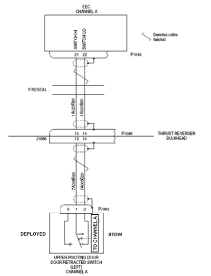
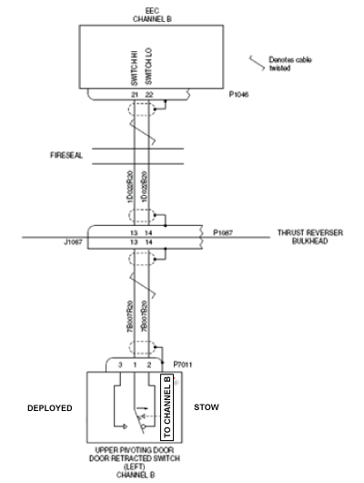
- Disconnect Upper Left Door Stow Switch connectors P7003 and P7011. Perform a continuity check on the stow switch while the TR door is stowed as follows:
From To Result J7003-1 J7003-2 J7011-1 J7011-2 - If there is no continuity, replace R TR upper left stow switch and do close out.
- If there is continuity, continue with next step.
- Disconnect R EEC connectors P1043 and P1046. Perform a continuity check as follows:
From To Result P7003-1 Ground P7003-2 Ground P7011-1 Ground P7011-2 Ground - If there is continuity, repair defective wiring as required and do close out.
- If there is no continuity, continue with next step.
- Perform a continuity check as follows:
From To Result P7003-1 P1043-21 P7003-2 P1043-22 P7011-1 P1046-21 P7011-2 P1046-22 - If there is no continuity, repair defective wiring as required and do close out.
- If there is continuity, continue with next step.
- Swap the R TR door upper left stow switch with L TR upper left stow switch.
- If the system checks are good, replace R TR upper left stow switch and do close out.
- If fault remains, continue with next step.
- Replace the Right EEC.
- Do close out.