10/09/19
Message Overview:
Fault Message:
R TR UPPER CH B WRG/LVT RNG
Fault Code:
7325715RBR
Associated CAS:
| Reporting LRU: | Right Engine Electronic Controller (EEC) |
| System Description: | 78-30-00 |
| Schematic Diagram: | 78-33-00 [ Global Express ] [ G5000 ] [ Global XRS ] |
| Wiring Diagram: | 78-33-02 [ Global Express ] [ G5000 ] [ Global XRS ] |
Fault Description:
The fault message is set when:
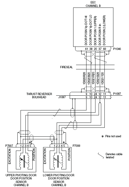
- There is an error of resistance or an open/short circuit in the primary or secondary coils of the Linear Variable Transformer (LVT) for channel B. This LVT is in the Door Position Sensor for the Upper Pivoting Door
- There is an open/short circuit in the interface wiring
Possible Causes:
- Door Position Sensor (LVT)
- Right Engine Electronic Controller (EEC)
- Associated Wiring
Troubleshooting Tips:
Advisory Wire/Service Bulletin: None
Forum Articles/Infoservice/Newsletter: None
These thrust reverser circuits are continuously monitored by the FADEC.Some of the door position sensor circuits for the lower and upper pivoting door are the same and cross-connected. This can cause the fault message CAIMS - L (R) TR LOWER CH B WRG/LVT RNG to be seen at the same time. If this occurs, do the fault isolation procedure for the door position sensor of the lower pivoting door at the same time as this procedure.
Quick Links:
| Opening of the Cowls | AMM 71-10-00-010-801 [ Global Express ] [ G5000 ] [ Global XRS ] |
| Closing of the Cowls | AMM 71-10-00-410-801 [ Global Express ] [ G5000 ] [ Global XRS ] |
| Thrust Reverser Safety Precautions | AMM 78-30-00-910-801 [ Global Express ] [ G5000 ] [ Global XRS ] |
| Deactivation of the Thrust Reverser (for Maintenance) | AMM 78-30-00-040-801 [ Global Express ] [ G5000 ] [ Global XRS ] |
| Activation of the Thrust Reverser (for Maintenance) | AMM 78-30-00-440-801 [ Global Express ] [ G5000 ] [ Global XRS ] |
| Removal of the Eng Electronic Controller (EEC) Mod 73-101559 |
EMM 73-21-01-000-801-B00 [ Global Express ] [ G5000 ] [ Global XRS ] |
| Installation of the Eng Electronic Controller (EEC) Mod 73-101559 |
EMM 73-21-01-400-801-B001 [ Global Express ] [ G5000 ] [ Global XRS ] |
| Removal of the Exhaust Access Panels | EMM 78-00-00-010-801 [ Global Express ] [ G5000 ] [ Global XRS ] |
| Installation of the Exhaust Access Panels | EMM 78-00-00-410-801 [ Global Express ] [ G5000 ] [ Global XRS ] |
| Removal of the Door Position Sensor | EMM 78-34-02-000-801 [ Global Express ] [ G5000 ] [ Global XRS ] |
| Installation of the Door Position Sensor | EMM 78-34-02-400-801 [ Global Express ] [ G5000 ] [ Global XRS ] |
| Wire Repair - Maintenance Practices - ALL | SPM 20-12-10-02 [ Global Express ] [ G5000 ] [ Global XRS ] |
Troubleshooting Recommendations:
CAUTION: DO NOT DO ELECTRICAL CHECKS INTO THE ENGINE ELECTRONIC CONTROLLER (EEC). IF YOU DO NOT OBEY THIS INSTRUCTION, DAMAGE TO THE EEC CAN OCCUR.
NOTE: It is necessary to disconnect connector P7001 from the door position sensor of the upper pivoting door before you do electrical checks. Some of the door position sensor circuits for the lower and upper pivoting door are the same and cross-connected.
- Perform the deactivation of the Thrust Reverser and open the Cowls.
- Perform a visual inspection of the interface wiring and connectors of the TR door position sensor circuit.
- If fault remains, rectify as required and go to step 6.
- If system checks are good, continue with next step.
- Perform a wiring check between the door position sensor (LVT) connector (P7007) and the right EEC (P1046).
- If wiring checks are not good, repair defective wiring as required and go to step 6.
- If wiring checks are good, continue with next step.
- Replace the upper TR door Position Sensor (LVT). Is the fault still present?
- If NO, go to step 6.
- If YES, continue with next step.
- Replace the right EEC.
- Close the cowls and perform the activation of the Thrust Reverser.
- Do close out.