

10/09/19
Message Overview:
Fault Message:
L TR ISOLATION CONTROL UNIT BLKG
Fault Code:
7325718LBR
Associated CAS:
| Reporting LRU: | Left Engine Electronic Controller (EEC) |
| System Description: | 78-30-00 |
| Schematic Diagram: | 78-33-00 [ Global Express ] [ G5000 ] [ Global XRS ] |
| Wiring Diagram: | 71-50-01 [ Global Express ] [ G5000 ] [ Global XRS ] 78-33-01 [ Global Express ] [ G5000 ] [ Global XRS ] |
Fault Description:
Thrust Reverser (TR) Isolation Control Unit (ICU), Isolation Valve (IV) pressure output disagrees with the ICU command.
Hydraulic Pressure Switch and Isolation Valve Fault Detection logic:
- Both Hydraulic Pressure Switch signals inside the ICU are compared with TR Isolation Valve command. If the two Switch contacts agree but disagree with the IV command then an Isolation Valve failure shall be flagged.
- If both Hydraulic Pressure Switch contacts, in one ICU disagree with each other, then a Switch fault is assumed.
- If IV Solenoid is energized and both Hydraulic Pressure Switch contacts indicate low pressure, but the doors still operate (LVTs indicating change from stowed to unstowed at 14% door open position or vice versa) then a failure of the Pressure Switches shall be assumed.
Possible Causes:
- Isolation Control Unit (ICU)
- Left Engine Electronic Controller (EEC)
- Associated Wiring
Troubleshooting Tips:
Advisory Wire/Service Bulletin: None
Forum Articles/Infoservice/Newsletter: None
Two hydraulic pressure switches are inside the Isolation Control Unit (ICU), one each switch feeding channel A, and B of the EEC’s. Two connectors, one for each channel. One ICU for RH side, one ICU for LH side. They live in the Aft. Equipment bay, and have the TR manual lock out lever on them. Pressure switch is open with no pressure. There is a small screen filter inside the ICU that when blocked can cause a problem. That is why the particle inspection is important. Ref. CMM 78-30-07.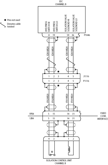
Quick Links:
| Opening of the Cowls | AMM 71-10-00-010-801 [ Global Express ] [ G5000 ] [ Global XRS ] |
| Closing of the Cowls | AMM 71-10-00-410-801 [ Global Express ] [ G5000 ] [ Global XRS ] |
| Deactivation of the Thrust Reverser (for Maintenance) | AMM 78-30-00-040-801 [ Global Express ] [ G5000 ] [ Global XRS ] |
| Activation of the Thrust Reverser (for Maintenance) | AMM 78-30-00-440-801 [ Global Express ] [ G5000 ] [ Global XRS ] |
| Removal of the Isolation Control Unit | AMM 78-33-01-000-801 [ Global Express ] [ G5000 ] [ Global XRS ] |
| Installation of the Isolation Control Unit | AMM 78-33-01-400-801 [ Global Express ] [ G5000 ] [ Global XRS ] |
| Isolation Control Unit | CMM 78-30-07 [ Global Express ] [ G5000 ] [ Global XRS ] |
| Removal of the Eng Electronic Controller (EEC) Mod 73-101559 |
EMM 73-21-01-000-801-B00 [ Global Express ] [ G5000 ] [ Global XRS ] |
| Installation of the Eng Electronic Controller (EEC) Mod 73-101559 |
EMM 73-21-01-400-801-B001 [ Global Express ] [ G5000 ] [ Global XRS ] |
| Wire Repair - Maintenance Practices - ALL | SPM 20-12-10-02 [ Global Express ] [ G5000 ] [ Global XRS ] |
Troubleshooting Recommendations:
- Visually verify ICU’s are not manually locked out. If they are, ensure TR’s are clear of equipment and personnel, and hydraulic systems are serviceable before unlocking.
- Verify no hydraulic leaks, and proper hydraulic quantity on hydraulic reservoirs.
- Move lock out lever back and forth to ensure free movement (about 15 lbf in), then leave in the normal (un-inhibited position).
- Inspect Connectors and sockets for damage, FOD.
- If there is a damage, repair as required and do close out.
- If there is no damage, continue with next step.
- Perform wiring checks for the affected ICU. Ensure both switches are open with no Hydraulic pressure. Switch is closed when hydraulic pressure is above 700 psig (about). Ensure pins to case are open (20 Megaohms). Clean and install connectors.
- If wiring checks are not good, repair defective wiring as required and do close out.
- If wiring checks are good, continue with next step.
- Visually inspect wire harnesses in aft equipment bay up to the pylon pass through.
- If system checks are good, do close out.
- If fault remains, continue with next step.
- Perform wiring checks between ICU to EEC. Move wire harnesses while doing the wring out, or use a megger.
- If wiring checks are not good, repair defective wiring as required and do close out.
- If wiring checks are good, continue with next step.
- Visually inspect engine wire harnesses from pylon to EEC. Look for signs of chafing and wire strain, especially inside or close to clamps, or tubing.
- If system checks are good, do close out.
- If fault remains, continue with next step.
- Swap ICU’s LH to RH. While swapping take a hydraulic sample at the ICU’s. Perform a particle inspection per NAS 1638 Class 9. Also do a acidity check of the hydraulic fluid at the valves. Any failures, flush the affected system.
- If system checks are good, replace left ICU and do close out.
- If fault remains, continue with next step.
- Replace Left EEC.
- Do close out.