

10/10/19
Message Overview:
Fault Message:
L TR UPPER L LOCK SW/WRG/P LOCK
Fault Code:
7325719LBR
Associated CAS:
| Reporting LRU: | Left Engine Electronic Controller (EEC) |
| System Description: | 78-30-00 |
| Schematic Diagram: | 78-34-00 [ Global Express ] [ G5000 ] [ Global XRS ] |
| Wiring Diagram: | 71-50-01 [ Global Express ] [ G5000 ] [ Global XRS ] |
Fault Description:
Left Engine Thrust Reverser (TR) Upper Left Door Stow Switch indicates that the door is not fully stowed when the TR is commanded stowed. When the LH Thrust Reverser has this fail message, the doors will stay in the current position.
Possible Causes:
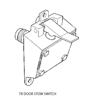
- Door Stow Switch
- Primary Lock Actuator
- Left Engine Electronic Controller (EEC)
- Associated Wiring
Troubleshooting Tips:
Advisory Wire/Service Bulletin: None
Forum Articles/Infoservice/Newsletter: None
- TR Stow switch is also called the TR retracted switch.
- These thrust reverser circuits are continuously monitored by the Engine EEC.
- There is good information in the CMM for the TR's. CMM 78-30-11 can be found in AeroManager (Rolls Royce Website). Door limits are found here.
Rolls-Royce NTO:
- NTO 066, Issue 4 - TRU Binding Primary Door Lock Mechanism
- NTO 135, Issue 1 - Issue of repeat Technical Variance 11595R (TR Stow Switch)
- Rolls-Royce SB-BR 700-78-101529- Replacement of PDLA
- Rolls Royce SB-BR700-78-900350-Inspection of PDLA
- Rolls Royce SB BR700-78-101635-Door Switch Water Ingress
- Rolls Royce SB BR700-78-900440-Inspection of TR
Quick Links:
| Access to Active Faults | AMM 45-45-00-970-802 [ Global Express ] [ G5000 ] [ Global XRS ] |
| Access to Stored Faults | AMM 45-45-00-970-803 [ Global Express ] [ G5000 ] [ Global XRS ] |
| Access to System Diagnostics | AMM 45-45-00-970-804 [ Global Express ] [ G5000 ] [ Global XRS ] |
| Opening of the Cowls | AMM 71-10-00-010-801 [ Global Express ] [ G5000 ] [ Global XRS ] |
| Closing of the Cowls | AMM 71-10-00-410-801 [ Global Express ] [ G5000 ] [ Global XRS ] |
| Thrust Reverser Safety Precautions | AMM 78-30-00-910-801 [ Global Express ] [ G5000 ] [ Global XRS ] |
| Deactivation of the Thrust Reverser (for Maintenance) | AMM 78-30-00-040-801 [ Global Express ] [ G5000 ] [ Global XRS ] |
| Activation of the Thrust Reverser (for Maintenance) | AMM 78-30-00-440-801 [ Global Express ] [ G5000 ] [ Global XRS ] |
| Visual Check of the Thrust Reverser System | AMM 78-30-00-210-807 [ Global Express ] [ G5000 ] [ Global XRS ] |
| Manual Opening of the Pivoting Doors | AMM 78-31-01-010-801 [ Global Express ] [ G5000 ] [ Global XRS ] |
| Manual Closing of the Pivoting Doors | AMM 78-31-01-410-801 [ Global Express ] [ G5000 ] [ Global XRS ] |
| Removal of the Eng Electronic Controller (EEC) Mod 73-101559 |
EMM 73-21-01-000-801-B00 [ Global Express ] [ G5000 ] [ Global XRS ] |
| Installation of the Eng Electronic Controller (EEC) Mod 73-101559 |
EMM 73-21-01-400-801-B001 [ Global Express ] [ G5000 ] [ Global XRS ] |
| Removal of the Exhaust Access Panels | EMM 78-00-00-010-801 [ Global Express ] [ G5000 ] [ Global XRS ] |
| Installation of the Exhaust Access Panels | EMM 78-00-00-410-801 [ Global Express ] [ G5000 ] [ Global XRS ] |
| Rigging check of the Pivoting Doors | EMM 78-31-01-220-801 [ Global Express ] [ G5000 ] [ Global XRS ] |
| Rigging of the Pivoting Doors | EMM 78-31-01-820-801 [ Global Express ] [ G5000 ] [ Global XRS ] |
| Removal of the Primary Lock Actuator and Mechanism | EMM 78-33-04-000-801 [ Global Express ] [ G5000 ] [ Global XRS ] |
| Installation of the Primary Lock Actuator and Mechanism | EMM 78-33-04-400-801 [ Global Express ] [ G5000 ] [ Global XRS ] |
| Removal of the Door Retracted Switch | EMM 78-34-01-000-801 [ Global Express ] [ G5000 ] [ Global XRS ] |
| Installation of the Door Retracted Switch | EMM 78-34-01-400-801 [ Global Express ] [ G5000 ] [ Global XRS ] |
| Wire Repair - Maintenance Practices - ALL | SPM 20-12-10-02 [ Global Express ] [ G5000 ] [ Global XRS ] |
Troubleshooting Recommendations:
- Using Active Faults, and CAIMS/System Diagnostics/ATA 73/EEC (affected channel)/LRU Test/Thrust Reverser Status, check LH upper T/R door locked status. If intermittent, check ground faults in System Diagnostics.
- Check door rigging, including distortion, debris, fluid, or damage around the TR door, and in the exhaust duct.
- If there is damage, repair as required and do close out.
- If there is no damage, continue with next step.
- Check primary lock actuator and mechanism for signs of corrosion, binding, incorrect assembly, or lack of lubrication, Refer the above SB’s. If you can not hydraulically open the LH TR’s, manually open LH TR’s, and lock out.
- Ensure TR door switch striker rollers are free to move, Lubricate if required. Rollers that are not free will cause a very intermittent fault.
- Perform a continuity check on the door stow switch connectors as follows. The TR Door switch has continuity when the switch is closed. Use freeze spray to simulate cold working environment on the switch. Verify Connector is clean and free of damage on the pins and sockets. Verify Switch has not been moved on its mounting due to damage, or incorrect assembly. Verify sealant integrity around TR Door Switch Body, ref BRR EMM.>
From To Result P7003-1 P7003-2 P7011-1 P7011-2 - If there is no continuity, repair defective wiring as required and do close out.
- If there is continuity, continue with next step.
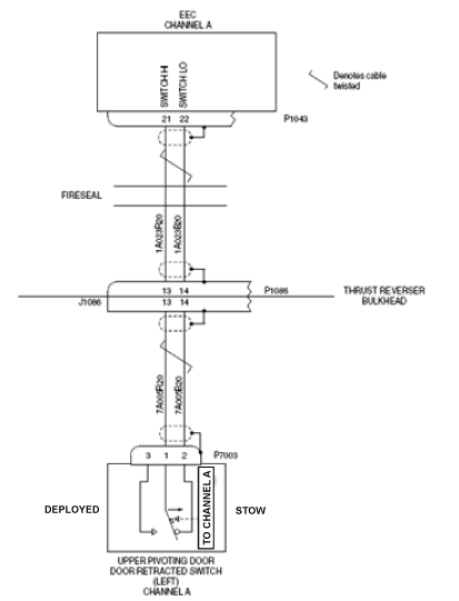
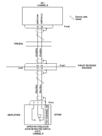
- Perform wiring checks between door stow switch and EEC.
- Connector P7003 to P1043 (CH A)
- Connector P7011 to P1046 (CH B)
- If wiring checks are not good, repair defective wiring as required and do close out.
- If wiring checks are good, continue with next step.
- Carry out a visual inspection of the interface wiring and connectors. Always respect the wire bundle radius requirements of the E.M.M., 5X or more the diameter of the wire bundle. Pay close attention to clamps and tubing pass by areas.
- If the system checks are good, do close out.
- If fault remains, continue with next step.
- With the TR buckets open verify the clearances of all the moving hinge points with the CMM. Grab the bucket and move it in all directions. Inspect all the Actuators for excessive leaking, and the actuator attach points for radial and axial clearances (CMM), and freedom of movement. Ensure the bucket is fitting into the Exhaust cutout straight and even. Remember, Leaking Hydraulic Fluid will wear away the lubrication of the hinge points.
- If the system checks are good, do close out.
- If fault remains, continue with next step.
- Replace door stow switch.
- If the system checks are good, do close out.
- If fault remains, continue with next step.
- Replace the Left EEC.
- Do close out.