10/09/19
Message Overview:
Fault Message:
L TR CH A WRG/ICU[PRESS SW] RNG MA
Fault Code:
7327224LBR
Associated CAS:
| Reporting LRU: | Left Engine Electronic Controller (EEC) |
| System Description: | 78-30-00 |
| Schematic Diagram: | 78-33-00 [ Global Express ] [ G5000 ] [ Global XRS ] |
| Wiring Diagram: | 71-50-01 [ Global Express ] [ G5000 ] [ Global XRS ] 78-33-01 [ Global Express ] [ G5000 ] [ Global XRS ] |
Fault Description:
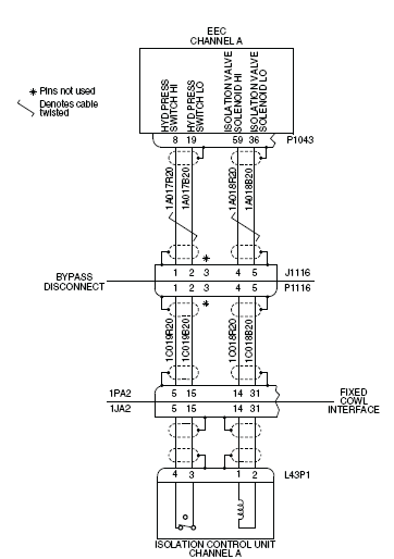
The fault message is set when the pressure switch of the Isolation Control Unit (ICU) for channel A gives an incorrect indication. The pressure switch sends a signal to channel A of the Engine Electronic Controller (EEC) that there is, or is not, hydraulic pressure available. These thrust reverser circuits are monitored by the Full-Authority Digital Engine-Controller (FADEC) when the thrust reverser is operated.
Possible Causes:
- Left Isolation Control Unit (ICU) (L43)
- Left Engine Electronic Controller (EEC)
- Associated Wiring
Troubleshooting Tips:
Advisory Wire/Service Bulletin: None
Forum Articles/Infoservice/Newsletter: None
These thrust reverser circuits are continuously monitored by the FADEC.
Quick Links:
| Opening of the Cowls | AMM 71-10-00-010-801 [ Global Express ] [ G5000 ] [ Global XRS ] |
| Closing of the Cowls | AMM 71-10-00-410-801 [ Global Express ] [ G5000 ] [ Global XRS ] |
| Deactivation of the Thrust Reverser (for Maintenance) | AMM 78-30-00-040-801 [ Global Express ] [ G5000 ] [ Global XRS ] |
| Activation of the Thrust Reverser (for Maintenance) | AMM 78-30-00-440-801 [ Global Express ] [ G5000 ] [ Global XRS ] |
| Thrust Reverser Safety Precautions | AMM 78-30-00 910-801 [ Global Express ] [ G5000 ] [ Global XRS ] |
| Removal of the Isolation Control Unit | AMM 78-33-01-000-801 [ Global Express ] [ G5000 ] [ Global XRS ] |
| Installation of the Isolation Control Unit | AMM 78-33-01-400-801 [ Global Express ] [ G5000 ] [ Global XRS ] |
| Removal of the Eng Electronic Controller (EEC) Mod 73-101559 |
EMM 73-21-01-000-801-B00 [ Global Express ] [ G5000 ] [ Global XRS ] |
| Installation of the Eng Electronic Controller (EEC) Mod 73-101559 |
EMM 73-21-01-400-801-B001 [ Global Express ] [ G5000 ] [ Global XRS ] |
| Wire Repair - Maintenance Practices - ALL | SPM 20-12-10-02 [ Global Express ] [ G5000 ] [ Global XRS ] |
Troubleshooting Recommendations:
CAUTION: DO NOT DO ELECTRICAL CHECKS INTO THE ENGINE ELECTRONIC CONTROLLER (EEC). IF YOU DO NOT OBEY THIS INSTRUCTION, DAMAGE TO THE EEC CAN OCCUR.
- Perform a visual inspection of the interface wiring and connectors for damage between the connectors (L43P1) and (P1043).
- If there is damage, repair as required and do close out.
- If there is no damage, continue with next step.
- Perform wiring checks between ICU (L43P1) and Fixed Cowl Interface (1JA2).
- If wiring checks are not good, repair defective wiring as required and do close out.
- If wiring checks are good, continue with next step.
- Perform wiring checks between Bypass Disconnect (P1116) and Fixed Cowl Interface (1PA2).
- If wiring checks are not good, repair defective wiring as required and do close out.
- If wiring checks are good, continue with next step.
- Perform wiring checks between Bypass Disconnect (J1116) and Left EEC (P1043).
- If wiring checks are not good, repair defective wiring as required and do close out.
- If wiring checks are good, continue with next step.
- Perform a check of the insulation resistance of the interface connectors ICU (L43P1), Bypass Disconnect (P1116) and Left EEC (P1043).
- If resistance checks are not good, repair defective wiring as required and do close out.
- If resistance checks are good, continue with next step.
- Swap Left EEC with Right EEC.
- If system checks are good, replace Left EEC and do close out.
- If fault remains, continue with next step.
- Replace Left ICU.
- Do close out.