10/09/19
Message Overview:
Fault Message:
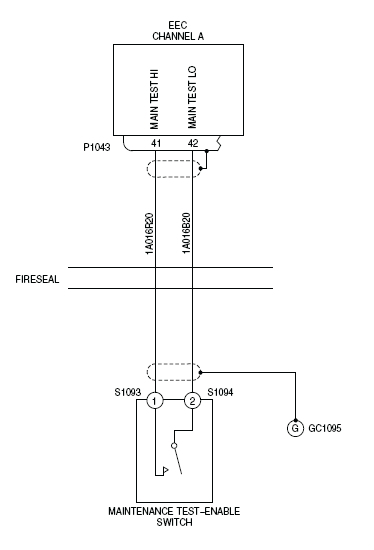
L MAINTENANCE TEST ENABLE SWITCH MA
Fault Code:
7327226LBR
Associated CAS:
| Reporting LRU: | Left Engine Electronic Controller (EEC) |
| System Description: | 78-30-00 |
| Schematic Diagram: | 78-33-00 [ Global Express ] [ G5000 ] [ Global XRS ] |
| Wiring Diagram: | 71-50-01 [ Global Express ] [ G5000 ] [ Global XRS ] 76-10-01 [ Global Express ] [ G5000 ] [ Global XRS ] |
Fault Description:
The fault message is set when there is an open/short circuit in the Maintenance Test-Enable Switch (MTES) or the interface wiring.
Possible Causes:
- Maintenance Test-Enable Switch (MTES)
- Left Engine Electronic Controller (EEC)
- Associated Wiring
Troubleshooting Tips:
Advisory Wire/Service Bulletin: None
Forum Articles/Infoservice/Newsletter: None
Quick Links:
| Opening of the Cowls | AMM 71-10-00-010-801 [ Global Express ] [ G5000 ] [ Global XRS ] |
| Closing of the Cowls | AMM 71-10-00-410-801 [ Global Express ] [ G5000 ] [ Global XRS ] |
| Deactivation of the Thrust Reverser (for Maintenance) | AMM 78-30-00-040-801 [ Global Express ] [ G5000 ] [ Global XRS ] |
| Activation of the Thrust Reverser (for Maintenance) | AMM 78-30-00-440-801 [ Global Express ] [ G5000 ] [ Global XRS ] |
| Removal of the Eng Electronic Controller (EEC) Mod 73-101559 |
EMM 73-21-01-000-801-B00 [ Global Express ] [ G5000 ] [ Global XRS ] |
| Installation of the Eng Electronic Controller (EEC) Mod 73-101559 |
EMM 73-21-01-400-801-B001 [ Global Express ] [ G5000 ] [ Global XRS ] |
| Wire Repair - Maintenance Practices - ALL | SPM 20-12-10-02 [ Global Express ] [ G5000 ] [ Global XRS ] |
Troubleshooting Recommendations:
CAUTION: DO NOT DO ELECTRICAL CHECKS INTO THE ENGINE ELECTRONIC CONTROLLER (EEC). IF YOU DO NOT OBEY THIS INSTRUCTION, DAMAGE TO THE EEC CAN OCCUR.
- Perform a visual inspection of the interface wiring and connectors for damage between MTES and EEC (P1043).
- If there is damage, repair as required and do close out.
- If there is no damage, continue with next step.
- Perform wiring checks between between the pins of the connector MTES and P1043 (EEC).
- If wiring checks are not good, repair defective wiring as required and do close out.
- If wiring checks are good, continue with next step.
- Connect the connector P1043 and the contacts S1093 and S1094, and the ground connector GC1095.
- If the fault message does not occur, do close out.
- If the fault message was stored, then the fault could be intermittent. Monitor the system to see if the fault message occurs again and continue with next step.
- Perform a check of the insulation resistance of the interface between S1093 and S1094, and the connector P1043.
- If there is damage, repair as required and do close out.
- If there is no damage, continue with next step.
- Replace MTES.
- If system checks are good, do close out.
- If fault remains, continue with next step.
- Replace Left EEC.
- Do close out.