06/22/21
Message Overview:
Message Name:
MULTIPLE SYSTEM FAILURES RELATED TO ONE SPDA
| Message Code: | 246OBS001 |
| Effectivity: | All |
| System: | DC Electrical Distribution |
| System Description: | 24-60-00 |
| Schematic Diagram: | 24-62-00 [ Global Express ] [ G5000 ] [ Global XRS ] 24-64-00 [ Global Express ] [ G5000 ] [ Global XRS ] |
| Wiring Diagram: | 24-62-05 [ Global Express ] [ G5000 ] [ Global XRS ] 24-64-01 [ Global Express ] [ G5000 ] [ Global XRS ] |
Message Description:
Multiple systems or Line Replaceable Units (LRU) have failed at the same time. These systems all have in common that they are being electrically fed by the same Secondary Power Distribution Assembly (SPDA).
Possible Causes:
- Secondary Power Distribution Assembly (SPDA) 1 (A13)
- Secondary Power Distribution Assembly (SPDA) 2 (A14)
- Secondary Power Distribution Assembly (SPDA) 3 (A15)
- Secondary Power Distribution Assembly (SPDA) 4 (A16)
- Alternate DC Power Distribution (ADCPD) 1 (AP73)
- Alternate DC Power Distribution (ADCPD) 2 (AP74)
- Alternate DC Power Distribution (ADCPD) 3 (AP75)
- Alternate DC Power Distribution (ADCPD) 4 (AP76)
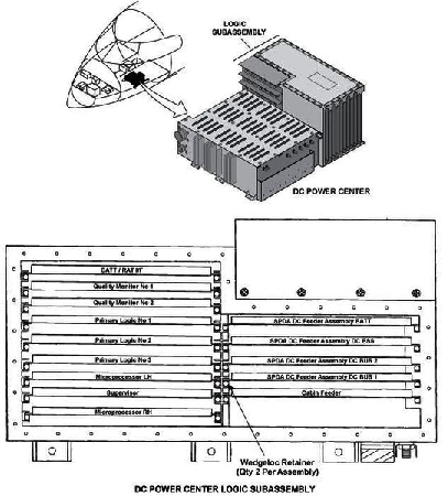
- DC Power Center (DCPC) (A63)
- Associated Wiring
Troubleshooting Tips:
Advisory Wire/Service Bulletin: None
Forum Articles/Infoservice/Newsletter: None
Quick Links:
| Removal of the DC Power Center (DCPC) | AMM 24-61-00-000-801 [ Global Express ] [ G5000 ] [ Global XRS ] |
| Installation of the DC Power Center (DCPC) | AMM 24-61-00-400-801 [ Global Express ] [ G5000 ] [ Global XRS ] |
| Removal of the Secondary-Power Distribution Assemblies | AMM 24-62-01-000-801 [ Global Express ] [ G5000 ] [ Global XRS ] |
| Installation of the Secondary-Power Distribution Assemblies | AMM 24-62-01-400-801 [ Global Express ] [ G5000 ] [ Global XRS ] |
| Functional Test of the DC Power Emergency Override System | AMM 24-64-00-720-801 [ Global Express ] [ G5000 ] [ Global XRS ] |
| Removal of the Alternate DC-Power Distribution (ADCPD) Panels No. 1 and No. 2 | AMM 24-65-01-000-801 [ Global Express ] [ G5000 ] [ Global XRS ] |
| Installation of the Alternate DC-Power Distribution (ADCPD) Panels No. 1 and No. 2 | AMM 24-65-01-400-801 [ Global Express ] [ G5000 ] [ Global XRS ] |
| Removal of the Alternate DC-Power Distribution (ADCPD) Panels No. 3 and No. 4 | AMM 24-65-01-000-802 [ Global Express ] [ G5000 ] [ Global XRS ] |
| Installation of the Alternate DC-Power Distribution (ADCPD) Panels No. 3 and No. 4 | AMM 24-65-01-400-802 [ Global Express ] [ G5000 ] [ Global XRS ] |
| Removal of the Alternate DC-Power Distribution (ADCPD) Panels No. 3 and No. 4 Relays (K54, K55, K56 and K57) |
AMM 24-65-01-000-803 [ Global Express ] [ G5000 ] [ Global XRS ] |
| Installation of the Alternate DC-Power Distribution (ADCPD) Panels No. 3 and No. 4 Relays (K54, K55, K56 and K57) |
AMM 24-65-01-400-803 [ Global Express ] [ G5000 ] [ Global XRS ] |
| Wire Repair - Maintenance Practices - ALL | SPM 20-12-10-02 [ Global Express ] [ G5000 ] [ Global XRS ] |
Troubleshooting Recommendations:
- Apply power to the aircraft. Wait for all the CAS messages to stabilize.
- Access the EMS CDU DC BUS page. Check whether all of the DC busses are IN.
- If NO, investigate the reason, set them IN and do close out.
- If YES, continue with next step.
- Set the EMER DC PWR switch to "OVRD". Check whether all of the CAS messages still present or not.
- If NO, set the EMER DC PWR switch back to normal mode and go to step 6.
- If YES, set the EMER DC PWR switch back to normal mode and continue with next step.
- Swap the SPDA associated to the failed systems with another SPDA.
- If the system checks are good, replace defective SPDA and do close out.
- If fault remains, continue with next step.
- Perform wiring checks between the affected SPDA and the associated ADCPD output.
- If wiring checks are not good, repair defective wiring as required and do close out.
- If wiring checks are good, continue with next step.
- Access ADCPD 3. Perform a voltage check for the associated SPDA as follows:
Associated SPDA From To Expected Result Result 1 TB19-1 Ground 28 VDC 2 TB19-2 Ground 28 VDC 3 TB19-3 Ground 28 VDC 4 TB19-4 Ground 28 VDC - If the voltage is not as specified, go to step 11.
- If the voltage is as specified, continue with next step.
- Perform a voltage check as follows:
Associated SPDA From To Expected Result Result 1 TB17-1 Ground 28 VDC 2 TB17-2 Ground 28 VDC 3 TB17-3 Ground 28 VDC 4 TB17-4 Ground 28 VDC - If the voltage is not as specified, go to step 10.
- If the voltage is as specified, continue with next step.
- Access ADCPD 4. Perform a voltage check for the associated SPDA as follows:
Associated SPDA From To Expected Result Result 1 TB18-1 Ground 28 VDC 2 TB18-2 Ground 28 VDC 3 TB18-3 Ground 28 VDC 4 TB18-4 Ground 28 VDC - If the voltage is not as specified, go to step 11.
- If the voltage is as specified, continue with next step.
- Perform a voltage check as follows:
Associated SPDA From To Expected Result Result 1 TB16-1 Ground 28 VDC 2 TB16-2 Ground 28 VDC 3 TB16-3 Ground 28 VDC 4 TB16-4 Ground 28 VDC - If the voltage is as specified, go to step 11.
- If the voltage is not as specified, continue with next step.
- Use the SSM 24-64-00 diagram to troubleshoot the relays inside the ADCPD. Check if any fault in the relays inside the ADCPD.
- If any fault in the relays found, replace defective relay/ADCPD and do close out.
- If no fault found, continue with next step.
- Perform a wiring check between the affected ADCPD and the associated DCPC output terminal.
- If the wiring checks are not good, repair defective wiring as required and do close out.
- If the wiring checks are good, continue with next step.
- Access the DCPC logic card assembly. Swap the SSPC card associated to the missing output.
- If the system checks are good, replace defective SSPC Card and do close out.
- If fault remains, continue with next step.
- Replace the DCPC.
- Do close out.