06/29/21
Message Overview:
Message Name:
HYD PUMP 2B CIRCUIT BREAKER TRIPPING
| Message Code: | 291OBS002 |
| Effectivity: | All |
| System: | Hydraulic Systems 1 and 2 |
| System Description: | 29-12-00 |
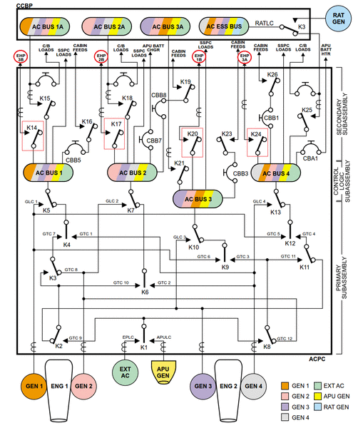
| Schematic Diagram: | 29-12-00 [ Global Express ] [ G5000 ] [ Global XRS ] |
| Wiring Diagram: | 29-00-04 [ Global Express ] [ G5000 ] [ Global XRS ] |
Message Description:
AC Power Center (ACPC) Secondary Logic Card (SLC) 2 reported AC Motor Pump (ACMP) 2B Circuit Breaker (CB) tripped.
Possible Causes:
- AC Power Center (ACPC) Relay (K17)
- AC Power Center (ACPC) Contactor (K7)
- AC Motor Pump (ACMP) 2B (B52)
- AC Power Center (ACPC) Secondary Logic Card (SLC) 2
- AC Power Center (ACPC) Electromagnetic Interface (EMI) Filter
- Hydraulic System 2 Manifold
- AC Power Center (ACPC) (A54)
- Associated Wiring
Troubleshooting Tips:
Advisory Wire/Service Bulletin: None
Forum Articles/Infoservice/Newsletter: None
Quick Links:
| Removal of the AC Power Center (ACPC) | AMM 24-51-00-000-801 [ Global Express ] [ G5000 ] [ Global XRS ] |
| Installation of the AC Power Center (ACPC) | AMM 24-51-00-400-801 [ Global Express ] [ G5000 ] [ Global XRS ] |
| Removal of the AC Power Center (ACPC) Secondary Logic |
AMM 24-51-13-000-801 [ Global Express ] [ G5000 ] [ Global XRS ] |
| Installation of the AC Power Center (ACPC) Secondary Logic |
AMM 24-51-13-400-801 [ Global Express ] [ G5000 ] [ Global XRS ] |
| Removal of the AC Power Center (ACPC) L-Series Contactors |
AMM 24-51-33-000-801 [ Global Express ] [ G5000 ] [ Global XRS ] |
| Installation of the AC Power Center (ACPC) L-Series Contactors |
AMM 24-51-33-400-801 [ Global Express ] [ G5000 ] [ Global XRS ] |
| Hydraulic Safety Precautions | AMM 29-00-00-910-801 [ Global Express ] [ G5000 ] [ Global XRS ] |
| Pressurize the No. 1 and No. 2 Hydraulic Systems | AMM 29-10-00-862-801 [ Global Express ] [ G5000 ] [ Global XRS ] |
| Release Hydraulic Pressure - No. 1 and No. 2 Hydraulic Systems |
AMM 29-10-00-862-802 [ Global Express ] [ G5000 ] [ Global XRS ] |
| Removal of the No. 1 and No. 2 Hydraulic-System AC-Motor-Driven Pumps |
AMM 29-12-05-000-801 [ Global Express ] [ G5000 ] [ Global XRS ] |
| Installation of the No. 1 and No. 2 Hydraulic-System AC-Motor-Driven Pumps |
AMM 29-12-05-400-801 [ Global Express ] [ G5000 ] [ Global XRS ] |
| Removal of the No. 1 and No. 2 Hydraulic-System Filter Manifolds |
AMM 29-12-09-000-801 [ Global Express ] [ G5000 ] [ Global XRS ] |
| Installation of the No. 1 and No. 2 Hydraulic-System Filter Manifolds |
AMM 29-12-09-400-801 [ Global Express ] [ G5000 ] [ Global XRS ] |
| Wire Repair - Maintenance Practices - ALL | SPM 20-12-10-02 [ Global Express ] [ G5000 ] [ Global XRS ] |
Troubleshooting Recommendations:
- Perform CAIMS Hydraulic Pump Phase Current Check:
NOTE: Perform this check if the hydraulic pump circuit breaker does not trip every time or if there is a delay between the time when the pump is turned ON and when the pump circuit breaker trips.- Using the PMAT, access CAIMS
- Select SYSTEM DIAG
- Select ATA 24
- Select AC POWER CENTER ACPC_A (B)
- Select LRU TEST
- Select HYDRAULIC PUMP SYSTEM DATA
- Select CONFIRM to go to page 2/4
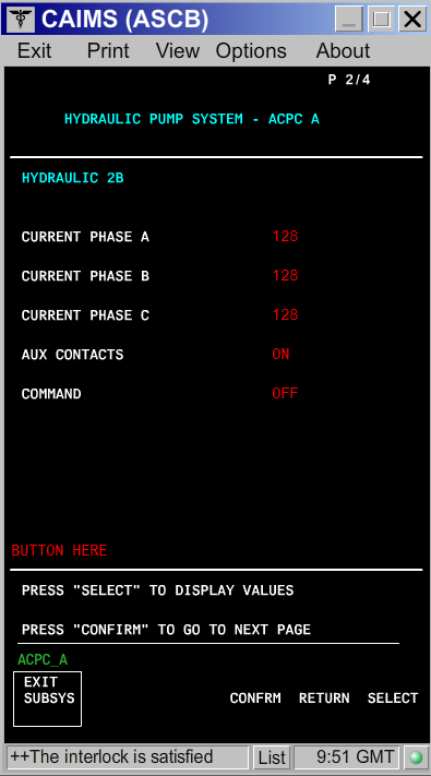
- Turn ON the hydraulic pump and look at the three phase's current value.
- If there is a phase (A, B or C) that displays no current or a different current value than the other two phases, continue with next step and if needed, go to step 8 and if still required go to step 23.
- If the current value is the same on all three phases, continue with next step.
- For hydraulic pump check, disconnect hydraulic pump 2B connector (B52P1).
- On the EMS CDU set the HYD PUMP 2B Circuit Breaker (CB) to IN.
- Set hydraulic pump 2B to ON via the Hydraulic Control Panel.
- Perform the voltage check as follows:
From To Expected Result Result B52P1-A B52P1-E 115 VAC B52P1-B B52P1-E 115 VAC B52P1-C B52P1-E 115 VAC - If the voltage is not as specified above or the circuit breaker is tripping, go to step 17.
- If the voltage is as specified above, continue with next step.
NOTE: Presence of voltage does not eliminate the electrical system as a possible cause. High resistance of a single phase contact on any multiphase contactor will cause the remaining phases to go HIGH. This will result in the CB tripping.
- Set hydraulic pump 2B to OFF.
- For hydraulic versus electrical Isolation Test, in the aft equipment bay, remove enough clamps to swap hydraulic pump 2B connector (B52P1) with hydraulic pump 1B connector (B51P1).
- If the system checks are good, replace hydraulic pump 2B connector (B52P1) and do close out.
- If fault remains, continue with next step.
- Using the EMS CDU, set hydraulic pump 2B and 1B CBs to IN.
- Set the hydraulic pump 1B switch to ON and monitor the hydraulic system 2 pressure and quantity on the EICAS.
- If the CB does not trip, go to step 13.
- If the HYD PUMP 1B circuit breaker trips, continue with next step.
- Replace hydraulic pump 2B.
- Connect the hydraulic pump connectors to their respective pump and test the system again.
- If the system checks are good, do close out.
- If the circuit breaker is still tripping, replace the hydraulic system 2 manifold and continue with next step.
- Set the hydraulic pump 1B switch to OFF.
- Set the hydraulic pump 2B switch to ON and monitor the hydraulic system 1 pressure and quantity on the EICAS.
- If the HYD PUMP 2B circuit breaker does not trip, check hydraulic pump 2B connector B52P1 and wiring for damage in the area of the removed clamps. Reconnect the connectors to their respective pump, test the system and do close out.
- If the HYD PUMP 2B circuit breaker trips, continue with next step.
- Connect the hydraulic pump connectors to their respective pump.
- Set the hydraulic pump 2B switch to OFF and continue with next step.
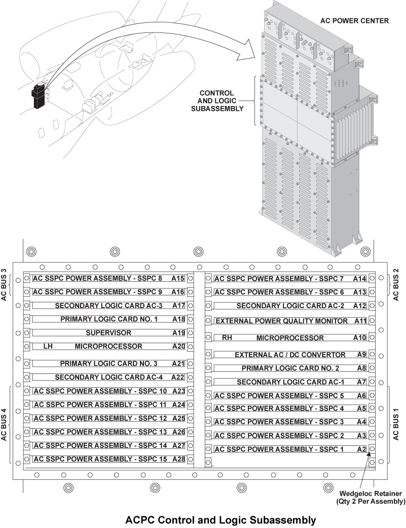
- For Secondary Logic Card, swap the ACPC Secondary Logic Card (SLC) 2 with SLC 3.
- If the system checks are good, replace ACPC Secondary Logic Card (SLC) 2 and do close out.
- If the fault remains, continue with next step.
- Reset the hydraulic pump 2B circuit breaker to IN.
- Set the hydraulic pump 2B switch to ON.
- If the HYD PUMP 2B circuit breaker trips, set the hydraulic pump 2B switch to OFF and go to step 23.
- If the HYD PUMP 2B circuit breaker does not trip, continue with next step.
- Set the hydraulic pump 2B switch to OFF.
- Set the hydraulic pump 1B switch to ON.
- If the HYD PUMP 1B circuit breaker does not trip, set the hydraulic pump 1B switch to OFF, do close out and monitor.
- If the HYD PUMP 1B circuit breaker trips, continue with next step.
- Set the hydraulic pump 1B switch to OFF.
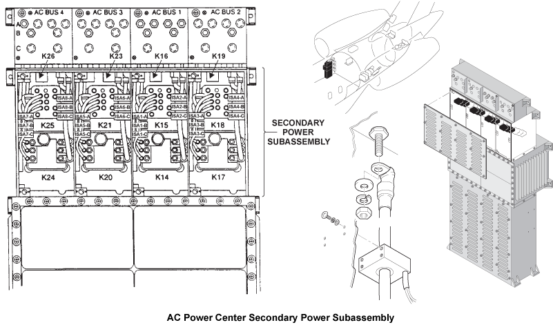
- For Relay and contactor check, access the ACPC secondary power assembly and swap relay K17 with relay K20.
NOTE: You may perform a 115 VAC voltage check directly on the contactors phase contacts to see if a phase is missing. If a phase is missing, check to see if problem originates upstream of the affected contactor. If the contactor is found to be causing the phase drop, replace contactor.- If the system checks are good, replace relay K17 and do close out.
- If fault remains, continue with next step.
- Reset the hydraulic pump 2B circuit breaker back to IN.
- Set the hydraulic pump 2B switch to ON.
- If the HYD PUMP 2B circuit breaker does not trip, set the pump to OFF, replace the defective relay and do close out.
- If the HYD PUMP 2B circuit breaker trips, set the hydraulic pump 2B switch to OFF and continue with next step.
- Access the ACPC primary power assembly and swap contactor K7 with K10.
- If the system checks are good, replace contactor K7 and do close out.
- If fault remains, continue with next step.
- Reset the hydraulic pump 2B circuit breaker back to IN.
- Set the hydraulic pump 2B switch to ON.
- If the HYD PUMP 2B circuit breaker does not trip, set the pump to OFF, replace the defective contactor and do close out.
- If the HYD PUMP 2B circuit breaker trips, set the hydraulic pump 2B switch to OFF and continue with next step.
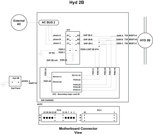
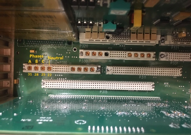
- For EMI filter check, perform a wiring check of the EMI filter.
NOTE: The picture 5 and 6 depicts SLC 3 connector P310 and is shown for reference since it has the same layout as SLC 2 connector P210.- If wiring checks are not good, repair defective wiring as required and do close out.
- If wiring checks are good, continue with next step.
- Remove SLC 2.
- Perform a continuity check for EMI filter as follows:
From To Result P210-22 Ground - If there is continuity, go to step 35.
- If there is no continuity, continue with next step.
- Perform a continuity check at connector P210 as follows:
From To Result P210-22 P210-25 P210-22 P210-28 P210-22 P210-31 - If there is no continuity, go to step 35.
- If there is continuity, continue with next step.
- Install SLC 2.
- Retest Hydraulic pump 2B.
- Replace ACPC.
- Do close out.