06/29/21
Message Overview:
Message Name:
HYD PUMP 3A CIRCUIT BREAKER TRIPPING
| Message Code: | 291OBS003 |
| Effectivity: | All |
| System: | Hydraulic System 3 |
| System Description: | 29-13-00 |
| Schematic Diagram: | 29-13-00 [ Global Express ] [ G5000 ] [ Global XRS ] |
| Wiring Diagram: | 29-00-05 [ Global Express ] [ G5000 ] [ Global XRS ] |
Message Description:
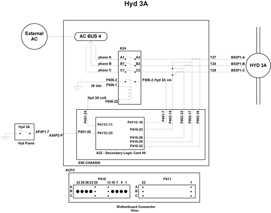
AC Power Center (ACPC) Secondary Logic Card (SLC) 4 reported AC Motor Pump (ACMP) 3A Circuit Breaker (CB) tripped.
Possible Causes:
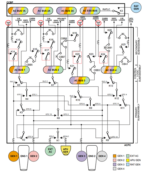
- AC Power Center (ACPC) Relay (K24)
- AC Power Center (ACPC) Contactor (K13)
- AC Motor Pump (ACMP) 3A (B53)
- AC Power Center (ACPC) Secondary Logic Card (SLC) 4
- AC Power Center (ACPC) Electromagnetic Interface (EMI) Filter
- AC Power Center (ACPC) (A54)
- Associated Wiring
Troubleshooting Tips:
Advisory Wire/Service Bulletin: None
Forum Articles/Infoservice/Newsletter: None
Quick Links:
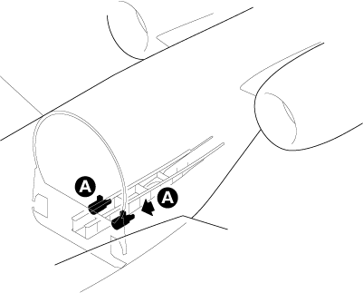
| Removal of the AC Power Center (ACPC) | AMM 24-51-00-000-801 [ Global Express ] [ G5000 ] [ Global XRS ] |
| Installation of the AC Power Center (ACPC) | AMM 24-51-00-400-801 [ Global Express ] [ G5000 ] [ Global XRS ] |
| Removal of the AC Power Center (ACPC) Secondary Logic |
AMM 24-51-13-000-801 [ Global Express ] [ G5000 ] [ Global XRS ] |
| Installation of the AC Power Center (ACPC) Secondary Logic |
AMM 24-51-13-400-801 [ Global Express ] [ G5000 ] [ Global XRS ] |
| Removal of the AC Power Center (ACPC) L-Series Contactors |
AMM 24-51-33-000-801 [ Global Express ] [ G5000 ] [ Global XRS ] |
| Installation of the AC Power Center (ACPC) L-Series Contactors |
AMM 24-51-33-400-801 [ Global Express ] [ G5000 ] [ Global XRS ] |
| Hydraulic Safety Precautions | AMM 29-00-00-910-801 [ Global Express ] [ G5000 ] [ Global XRS ] |
| Pressurize the No. 3 Hydraulic System | AMM 29-10-00-862-803 [ Global Express ] [ G5000 ] [ Global XRS ] |
| Release Hydraulic Pressure - No. 3 Hydraulic System | AMM 29-10-00-862-804 [ Global Express ] [ G5000 ] [ Global XRS ] |
| Removal of the No. 3 Hydraulic-System AC-Motor-Driven Pumps |
AMM 29-13-01-000-801 [ Global Express ] [ G5000 ] [ Global XRS ] |
| Installation of the No. 3 Hydraulic-System AC-Motor-Driven Pumps |
AMM 29-13-01-400-801 [ Global Express ] [ G5000 ] [ Global XRS ] |
| Removal of the No. 3 Hydraulic-System Filter Manifold |
AMM 29-13-05-000-801 [ Global Express ] [ G5000 ] [ Global XRS ] |
| Installation of the No. 3 Hydraulic-System Filter Manifold |
AMM 29-13-05-400-801 [ Global Express ] [ G5000 ] [ Global XRS ] |
| Wire Repair - Maintenance Practices - ALL | SPM 20-12-10-02 [ Global Express ] [ G5000 ] [ Global XRS ] |
Troubleshooting Recommendations:
- Perform CAIMS Hydraulic Pump Phase Current Check:
NOTE: Perform this check if the hydraulic pump circuit breaker does not trip every time or if there is a delay between the time when the pump is turned ON and when the pump circuit breaker trips.- Using the PMAT, access CAIMS
- Select SYSTEM DIAG
- Select ATA 24
- Select AC POWER CENTER ACPC_A (B)
- Select LRU TEST
- Select HYDRAULIC PUMP SYSTEM DATA
- Select CONFIRM to go to page 3/4
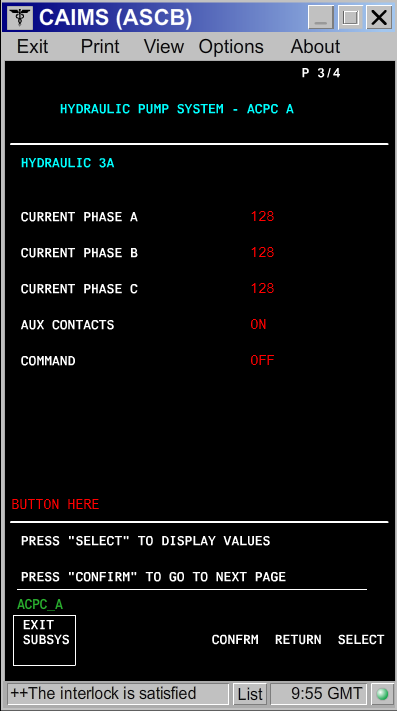
- Turn ON the hydraulic pump and look at the three phase's current value.
- If there is a phase (A, B or C) that displays no current or a different current value than the other two phases, continue with next step and if needed, go to step 8 and if still required go to step 16.
- If the current value is the same on all three phases, continue with next step.
- For hydraulic pump check, disconnect hydraulic pump 3A connector (B53P1).
- On the EMS CDU set the HYD PUMP 3A Circuit Breaker (CB) to IN.
- Set hydraulic pump 3A to ON via the Hydraulic Control Panel.
- Perform the voltage check as follows:
From To Expected Result Result B53P1-A B53P1-E 115 VAC B53P1-B B53P1-E 115 VAC B53P1-C B53P1-E 115 VAC - If the voltage is not as specified above or the circuit breaker is tripping, go to step 10.
- If the voltage is as specified above, continue with next step.
NOTE: Presence of voltage does not eliminate the electrical system as a possible cause. High resistance of a single phase contact on any multiphase contactor will cause the remaining phases to go HIGH. This will result in the CB tripping.
- Set hydraulic pump 3A to OFF.
- For hydraulic versus electrical Isolation Test, with hydraulic pump 3A switch set to OFF, perform a continuity check between B53P1 connectors as follows:
From To Expected Result Result B53P1-A B53P1-E Open B53P1-B B53P1-E Open B53P1-C B53P1-E Open B53P1-A B53P1-B Open B53P1-A B53P1-C Open B53P1-B B53P1-C Open - If there is continuity, repair defective wiring as required and do close out.
- If there is no continuity, continue with next step.
- After all the other checks in the sections below have been performed, if a cause was not identified, you may elect to swap hydraulic pump 3A and 3B to isolate if the pump is defective.
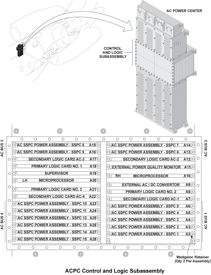
- For Secondary Logic Card, swap the ACPC Secondary Logic Card (SLC) 4 with SLC 1.
- If the system checks are good, replace ACPC Secondary Logic Card (SLC) 4 and do close out.
- If the fault remains, continue with next step.
- Reset the hydraulic pump 3A circuit breaker to IN.
- Set the hydraulic pump 3A switch to ON.
- If the HYD PUMP 3A circuit breaker trips, set the hydraulic pump 3A switch to OFF and go to step 16.
- If the HYD PUMP 3A circuit breaker does not trip, continue with next step.
- Set the hydraulic pump 3A switch to OFF.
- Set the hydraulic pump 3B switch to ON.
- If the HYD PUMP 3B circuit breaker does not trip, set the hydraulic pump 3B switch to OFF, do close out and monitor.
- If the HYD PUMP 3B circuit breaker trips, continue with next step.
- Set the hydraulic pump 3B switch to OFF.
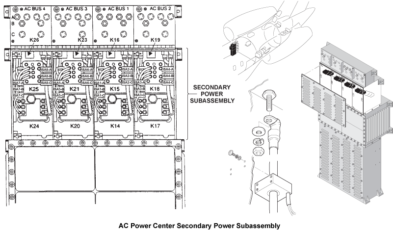
- For Relay and contactor check, access the ACPC secondary power assembly and swap relay K24 with relay K14.
NOTE: You may perform a 115 VAC voltage check directly on the contactors phase contacts to see if a phase is missing. If a phase is missing, check to see if problem originates upstream of the affected contactor. If the contactor is found to be causing the phase drop, replace contactor.- If the system checks are good, replace relay K24 and do close out.
- If fault remains, continue with next step.
- Reset the hydraulic pump 3A circuit breaker back to IN.
- Set the hydraulic pump 3A switch to ON.
- If the HYD PUMP 3A circuit breaker does not trip, set the pump to OFF, replace the defective relay and do close out.
- If the HYD PUMP 3A circuit breaker trips, set the hydraulic pump 3A switch to OFF and continue with next step.
- Access the ACPC primary power assembly and swap contactor K13 with K5.
- If the system checks are good, replace contactor K13 and do close out.
- If fault remains, continue with next step.
- Reset the hydraulic pump 3A circuit breaker back to IN.
- Set the hydraulic pump 3A switch to ON.
- If the HYD PUMP 3A circuit breaker does not trip, set the pump to OFF, replace the defective contactor and do close out.
- If the HYD PUMP 3A circuit breaker trips, set the hydraulic pump 3A switch to OFF and continue with next step.
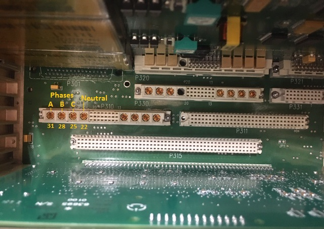
- For EMI filter check, perform a wiring check of the EMI filter.
NOTE: The picture 5 and 6 depicts SLC 3 connector P310 and is shown for reference since it has the same layout as SLC 4 connector P410.- If wiring checks are not good, repair defective wiring as required and do close out.
- If wiring checks are good, continue with next step.
- Remove SLC 4.
- Perform a continuity check at connector P410 as follows:
From To Result P410-22 Ground - If there is continuity, go to step 28.
- If there is no continuity, continue with next step.
- Perform a continuity check at connector P410 as follows:
From To Result P410-22 P410-25 P410-22 P410-28 P410-22 P410-31 - If there is no continuity, go to step 28.
- If there is continuity, continue with next step.
- Install SLC 4.
- Retest Hydraulic pump 3A.
- Replace ACPC.
- Do close out.