

06/29/21
Message Overview:
Message Name:
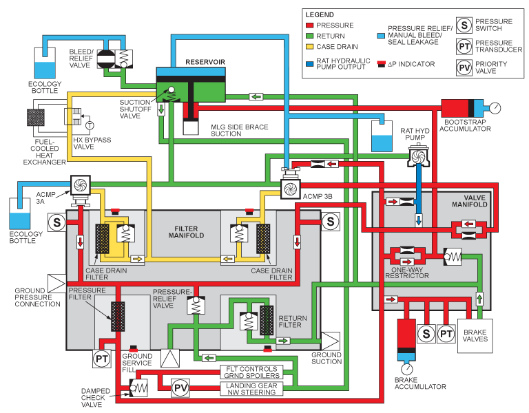
HYD SYNOPTIC PAGE - BOTH 3A AND 3B FLOW TUBES GREEN ON WITH ONLY ONE PUMP ON
| Message Code: | 291OBS005 |
| Effectivity: | All |
| System: | Hydraulic System 3 |
| System Description: | 29-13-00 |
| Schematic Diagram: | 29-13-00 [ Global Express ] [ G5000 ] [ Global XRS ] |
| Wiring Diagram: | 29-00-05 [ Global Express ] [ G5000 ] [ Global XRS ] |
Message Description:
When either Hydraulic Pump 3A or 3B is on, hydraulic pressure and green flow tube on hydraulic synoptic page is displayed on opposite side.
Possible Causes:
- AC Motor Pump 3A Pressure Switch (S39)
- AC Motor Pump 3B Pressure Switch (S40)
- Hydraulic System 3 Filter Manifold
- Associated Wiring
Troubleshooting Tips:
Quick Links:
| Hydraulic Safety Precautions | AMM 29-00-00-910-801 [ Global Express ] [ G5000 ] [ Global XRS ] |
| Hydraulic Technical Precautions | AMM 29-00-00-910-802 [ Global Express ] [ G5000 ] [ Global XRS ] |
| Pressurize the No. 3 Hydraulic System | AMM 29-10-00-862-803 [ Global Express ] [ G5000 ] [ Global XRS ] |
| Release Hydraulic Pressure - No. 3 Hydraulic System |
AMM 29-10-00-862-804 [ Global Express ] [ G5000 ] [ Global XRS ] |
| Removal of the No. 3 Hydraulic-System Filter Manifold |
AMM 29-13-05-000-801 [ Global Express ] [ G5000 ] [ Global XRS ] |
| Installation of the No. 3 Hydraulic-System Filter Manifold |
AMM 29-13-05-400-801 [ Global Express ] [ G5000 ] [ Global XRS ] |
| Removal of the Hydraulic Pressure Switches | AMM 29-31-05-000-801 [ Global Express ] [ G5000 ] [ Global XRS ] |
| Installation of the Hydraulic Pressure Switches | AMM 29-31-05-400-801 [ Global Express ] [ G5000 ] [ Global XRS ] |
| Wire Repair - Maintenance Practices - ALL | SPM 20-12-10-02 [ Global Express ] [ G5000 ] [ Global XRS ] |
Troubleshooting Recommendations:
- On the Hydraulic HYD synoptic page observe the results of the following tests.
- Turn ON both System 3 HYD pumps. Make sure both flow tubes are green.
- Shut one HYD pump OFF.
- If both flow tubes are still green, go to step 6.
- If the flow tube on the OFF side extinguished (empty), continue with next step.
- Turn both pumps ON again and shut the opposite pump OFF this time.
- Confirm both flow tubes are still green (filled).
- Shut both HYD pumps.
- If both Flow tubes extinguish (empty), replace the HYD system 3 filter manifold and do close out.
- If one flow tube remains green (filled), continue with next step.
- Perform a wiring check between the affected side pressure switch and DAU 4.
- If wiring checks are not good, repair defective wiring as required and do close out.
- If wiring checks are good, continue with next step.
- Replace the affected side pressure switch.
- Do close out.