

06/30/21
Message Overview:
Message Name:
ALL NAV LIGHTS DO NOT ILLUMINATE
| Message Code: | 334OBS001 |
| Effectivity: | All |
| System: | Navigation Lighting System |
| System Description: | 33-42-00 |
| Schematic Diagram: | 33-42-00 [ Global Express ] [ G5000 ] [ Global XRS ] |
| Wiring Diagram: | 33-42-01 [ Global Express ] [ G5000 ] [ Global XRS ] |
Message Description:
All the Navigation Light do not come ON.
Possible Causes:
- Navigation Light Control Panel (AP11)
- Navigation Light Switch (S1)
- Failure Indicator Box (A126)
- Electrical Management System Control and Display Unit (EMS CDU) 1 (A94)
- Electrical Management System Control and Display Unit (EMS CDU) 2 (A91)
- Secondary Power Distribution Assembly (SPDA) 3 (A15)
- Associated Wiring
Troubleshooting Tips:
Advisory Wire/Service Bulletin: None
Forum Articles/Infoservice/Newsletter: None
Quick Links:
| Removal of the Secondary-Power Distribution Assemblies | AMM 24-62-01-000-801 [ Global Express ] [ G5000 ] [ Global XRS ] |
| Installation of the Secondary-Power Distribution Assemblies | AMM 24-62-01-400-801 [ Global Express ] [ G5000 ] [ Global XRS ] |
| Removal of the Electrical Management System Control-and-Display Units (EMS CDU) | AMM 24-70-01-000-801 [ Global Express ] [ G5000 ] [ Global XRS ] |
| Installation of the Electrical Management System Control-and-Display Units (EMS CDU) | AMM 24-70-01-400-801 [ Global Express ] [ G5000 ] [ Global XRS ] |
| Removal of the Failure Indicator Box | AMM 33-42-13-000-801 [ Global Express ] [ G5000 ] [ Global XRS ] |
| Installation of the Failure Indicator Box | AMM 33-42-13-400-801 [ Global Express ] [ G5000 ] [ Global XRS ] |
| Wire Repair - Maintenance Practices - ALL | SPM 20-12-10-02 [ Global Express ] [ G5000 ] [ Global XRS ] |
Troubleshooting Recommendations:
- Make sure the aircraft power is not set to "Ground service" mode and set the NAV light switch to ON.
- Record label and bits status through the EMS CDU Signboard menu as follows:
- Select SYSTEM - CNTL key
- Select lower left Line Select Key (LSK)
- Select lower right LSK
- Select "SPDA 3 IN"
- Record label 046
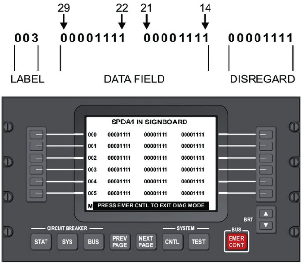
Left Column Center Column 29 28 27 26 25 24 23 22 21 20 19 18 17 16 15 14 046
- Examine bits 29, 26, 25, 24, 23 and 22.
- If bits 26, 25, 24, 23 or 22 are set to "0", go to step 6.
- If bit 29 is set to "1", go to step 9.
- If bits 26, 25, 24, 23 or 22 are set to "1", continue with next step.
- Disconnect the NAV lights control and indication unit connector A126P1. Check the 28 VDC power input from SPDA 3 as follows:
From To Expected Result Result A126P1-A A126P1-P 28 VDC - If there is no 28 VDC, repair or replace the defective wiring as required and do close out.
- If there is 28 VDC, continue with next step.
- Replace NAV light indicator unit.
- If system checks are good, do close out.
- If fault remains, continue with next step.
- The SPDA is not supplying power. Swap SPDA 3 with SPDA 4. Is the fault still present?
- If NO, replace SPDA 3 and do close out.
- If YES, continue with next step.
- Disconnect EMS CDU 1 connector A94P1 and EMS CDU 2 connector A91P1. Perform a continuity check between EMS CDU and ground as follows:
From To Result A94P1-49 Ground A91P1-49 Ground - If there is continuity, repair or replace the defective wiring as required and do close out.
- If there is no continuity, continue with next step.
- Perform a continuity check between the EMS CDUs and SPDA 3 as follows and repair defective wiring as required
From To Result A91P1-7 A15P6-1 A91P1-8 A15P6-2 A94P1-7 A15P5-1 A94P1-8 A15P5-2 - If there is no continuity, repair or replace the defective wiring as required and do close out.
- If there is continuity, continue with next step.
- Replace defective EMS CDU.
- Do close out.