

06/30/21
Message Overview:
Message Name:
WING INSPECTION LIGHTS UNSERVICEABLE
| Message Code: | 334OBS014 |
| Effectivity: | All |
| System: | Wing Inspection Lighting System |
| System Description: | 33-45-00 |
| Schematic Diagram: | 33-45-00 [ Global Express ] [ G5000 ] [ Global XRS ] |
| Wiring Diagram: | 33-45-01 [ Global Express ] [ G5000 ] [ Global XRS ] |
Message Description:
Wing Inspection Light or Lights do not come ON.
Possible Causes:
- Wing Inspection Light Bulb
- Left Wing Inspection Light (DS1)
- Right Wing Inspection Light (DS2)
- Wing Inspection Light Switch (S4)
- External Lights Control Panel (AP56)
- Secondary Power Distribution Assembly (SPDA) 3 (A15)
- Secondary Power Distribution Assembly (SPDA) 4 (A16)
- Associated Wiring
Troubleshooting Tips:
Advisory Wire/Service Bulletin: None
Forum Articles/Infoservice/Newsletter: None
Quick Links:
| Connect Electrical Power to the Aircraft | AMM 24-00-00-861-801 [ Global Express ] [ G5000 ] [ Global XRS ] |
| Remove the Electrical Power from the Aircraft | AMM 24-00-00-861-802 [ Global Express ] [ G5000 ] [ Global XRS ] |
| Opening of Non-Thermal Circuit Breakers | AMM 24-00-00-863-801 [ Global Express ] [ G5000 ] [ Global XRS ] |
| Closing of Non-Thermal Circuit Breakers | AMM 24-00-00-863-802 [ Global Express ] [ G5000 ] [ Global XRS ] |
| Electrical/Electronic Safety Precautions | AMM 24-00-00-910-801 [ Global Express ] [ G5000 ] [ Global XRS ] |
| Removal of the Secondary-Power Distribution Assemblies | AMM 24-62-01-000-801 [ Global Express ] [ G5000 ] [ Global XRS ] |
| Installation of the Secondary-Power Distribution Assemblies | AMM 24-62-01-400-801 [ Global Express ] [ G5000 ] [ Global XRS ] |
| Removal of the Electrical Management System Control-and-Display Units (EMS CDU) |
AMM 24-70-01-000-801 [ Global Express ] [ G5000 ] [ Global XRS ] |
| Installation of the Electrical Management System Control-and-Display Units (EMS CDU) |
AMM 24-70-01-400-801 [ Global Express ] [ G5000 ] [ Global XRS ] |
| Removal of the EXTERNAL LIGHTS Control Panel | AMM 33-40-01-000-801 [ Global Express ] [ G5000 ] [ Global XRS ] |
| Installation of the EXTERNAL LIGHTS Control Panel | AMM 33-40-01-400-801 [ Global Express ] [ G5000 ] [ Global XRS ] |
| Operational Test of the Wing Inspection Lights | AMM 33-45-00-710-801 [ Global Express ] [ G5000 ] [ Global XRS ] |
| Removal of the Wing Inspection Lights | AMM 33-45-01-000-801 [ Global Express ] [ G5000 ] [ Global XRS ] |
| Installation of the Wing Inspection Lights | AMM 33-45-01-400-801 [ Global Express ] [ G5000 ] [ Global XRS ] |
| Replacement of the Wing Inspection Light-Bulb | AMM 33-45-01-960-801 [ Global Express ] [ G5000 ] [ Global XRS ] |
| Switches, Potentiometers,Switch/Lights and Bulbs - System Description |
SPM 20-11-00-01 [ Global Express ] [ G5000 ] [ Global XRS ] |
| Wire Repair - Maintenance Practices - ALL | SPM 20-12-10-02 [ Global Express ] [ G5000 ] [ Global XRS ] |
Troubleshooting Recommendations:
- Set the Wing inspection light switch to ON.
- If the LEFT Wing inspection light does not illuminate, go to step 7.
- If the RIGHT Wing inspection light does not illuminate, go to step 10.
- If BOTH LEFT and RIGHT wing inspection lights do not illuminate, continue with next step.
- On the EMS CDU, check and make sure the WING INSPECT LTS CB is set to IN.
NOTE: Please note that there are two Wing inspection lights CB. Depending on aircraft effectivity, make sure the correct one is set to IN.- 9002-9126 - DC BUS 1 SPDA 3- 9127-and up - DC BUS 1 SPDA 4- If the CB is OUT, investigate the reason and set to IN if possible.
- If the CB is already IN, continue with next step.
- Using the PMAT, access CAIMS, SYSTEM DIAGNOSTICS, ATA 24, SPDA 3A, LRU TEST. Select SPDA LOAD STATUS LABEL 020-027 and advance to page 14 of 16. Use the table below to check the status:
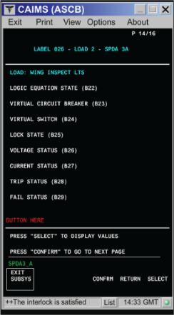
SPDA 3 Load 2: Wing Inspect LTS Expected Result Result Logic Equation State ON Virtual Circuit Breaker IN Virtual Switch ON Lock State Unlocked Voltage Status Present Current Status Flowing Trip Status Not Tripped FAIL Status Not Failed - If one or more value is not as table above, go to step 6.
- If all values are as table above, continue with next step.
- Swap SPDA 3 with SPDA 1 or SPDA 4 with SPDA 2 (see note at step 2). Is the fault still present?
- If NO, replace defective SPDA and do close out.
- If YES, continue with next step.
- Remove EMS CDU 1 and EMS CDU 2. Toggle the Wing inspection lights switch to ON and perform a continuity check as follows:
From To Result A91P2-58 Ground A94P2-58 Ground - If there is no continuity to ground, repair defective wiring or replace the Wing inspection Lights switch (S4) as required and do close out.
- If there is continuity, continue with next step.
- Perform a wiring check between SPDA 3 connector (A15P2) or SPDA 4 connector (A16P1) (see note at step 2) and both Wing inspection lights connector (DS1P1 and DS2P1) as follows:
From To Result A15P2-m DS1P1-A A15P2-m DS2P1-A A16P1-h DS1P1-A A16P1-h DS2P1-A - If wiring checks are not good, repair defective wiring as required and do close out.
- If wiring checks are good, continue with next step.
- Check the left Wing inspection light bulb.
- If the light bulb is not good, replace left Wing inspection light bulb and do close out.
- If the light bulb is operational, continue with next step.
- Perform a continuity check between the left Wing inspection light and the SPDA as follows:
Aircraft 9002-9126:From To Result DS1P1-A A15P1-m DS1P1-B Ground
Aircraft 9127 and subs:From To Result DS1P1-A A16P1-h DS1P1-B Ground - If there is no continuity, repair defective wiring as required and do close out.
- If there is continuity, continue with next step.
- Remove EMS CDU 1 and EMS CDU 2. Toggle the Wing inspection lights switch to ON and perform a continuity check as follows:
From To Result A91P2-58 Ground A94P2-58 Ground - If there is no continuity to ground, repair defective wiring as required or go to step 14.
- If there is continuity, replace the left Wing inspection light assembly and do close out.
- Check the right Wing inspection light bulb.
- If the light bulb is not good, replace right Wing inspection light bulb and do close out.
- If the light bulb is operational, continue with next step.
- Perform a continuity check between the right Wing inspection light and the SPDA as follows:
Aircraft 9002-9126:From To Result DS2P1-A A15P2-m DS2P1-B Ground
Aircraft 9127 and subs:From To Result DS2P1-A A16P1-h DS2P1-B Ground - If there is no continuity, repair defective wiring as required and do close out.
- If there is continuity, continue with next step.
- Remove EMS CDU 1 and EMS CDU 2. Toggle the Wing inspection lights switch to ON and perform a continuity to ground check as follows:
From To Result A91P2-58 Ground A94P2-58 Ground - If there is no continuity, repair defective wiring as required and do close out.
- If there is continuity, continue with next step.
- Replace the right Wing inspection light assembly.
- If system checks are good, do close out.
- If fault remains, continue with next step.
- Replace the Wing inspection Lights switch (S4).
- Do close out.