06/30/21
Message Overview:
Message Name:
WING LANDING/TAXI LIGHTS UNSERVICEABLE
| Message Code: | 334OBS015 |
| Effectivity: | All |
| System: | Landing And Taxi Lighting System |
| System Description: | 33-41-00 |
| Schematic Diagram: | 33-41-00 [ Global Express ] [ G5000 ] [ Global XRS ] |
| Wiring Diagram: | 33-41-01 [ Global Express ] [ G5000 ] [ Global XRS ] |
Message Description:
Wing landing/taxi (taxi/recognition) Light or Lights do not come ON.
Possible Causes:
- Left Wing Landing/Taxi Light (DS31)
- Right Wing Landing/Taxi Light (DS30)
- Wing Landing/Taxi Light Bulb
- Left Wing Landing Light Switch (S6)
- Left Wing Landing Light Switch (S8)
- Taxi/Recog Light Switch (S9)
- ACPC Logic Assembly (A54)
- Associated Wiring
Troubleshooting Tips:
Advisory Wire/Service Bulletin: None
Forum Articles/Infoservice/Newsletter: None
Quick Links:
| Connect Electrical Power to the Aircraft | AMM 24-00-00-861-801 [ Global Express ] [ G5000 ] [ Global XRS ] |
| Remove the Electrical Power from the Aircraft | AMM 24-00-00-861-802 [ Global Express ] [ G5000 ] [ Global XRS ] |
| Opening of Non-Thermal Circuit Breakers | AMM 24-00-00-863-801 [ Global Express ] [ G5000 ] [ Global XRS ] |
| Closing of Non-Thermal Circuit Breakers | AMM 24-00-00-863-802 [ Global Express ] [ G5000 ] [ Global XRS ] |
| Electrical/Electronic Safety Precautions | AMM 24-00-00-910-801 [ Global Express ] [ G5000 ] [ Global XRS ] |
| Removal of the Secondary-Power Distribution Assemblies | AMM 24-62-01-000-801 [ Global Express ] [ G5000 ] [ Global XRS ] |
| Installation of the Secondary-Power Distribution Assemblies | AMM 24-62-01-400-801 [ Global Express ] [ G5000 ] [ Global XRS ] |
| Removal of the EXTERNAL LIGHTS Control Panel | AMM 33-40-01-000-801 [ Global Express ] [ G5000 ] [ Global XRS ] |
| Installation of the EXTERNAL LIGHTS Control Panel | AMM 33-40-01-400-801 [ Global Express ] [ G5000 ] [ Global XRS ] |
| Removal of the Wing Landing/Taxi Lights | AMM 33-41-01-000-801 [ Global Express ] [ G5000 ] [ Global XRS ] |
| Installation of the Wing Landing/Taxi Lights | AMM 33-41-01-400-801 [ Global Express ] [ G5000 ] [ Global XRS ] |
| Replacement of the Wing Landing/Taxi Light-Bulb | AMM 33-41-01-960-801 [ Global Express ] [ G5000 ] [ Global XRS ] |
| Operational Test of the Wing Landing/Taxi Lights | AMM 33-41-01-710-801 [ Global Express ] [ G5000 ] [ Global XRS ] |
| Safety Precautions - Maintenance Practices - ALL | SPM 20-00-01-02 [ Global Express ] [ G5000 ] [ Global XRS ] |
| Wire Repair - Maintenance Practices - ALL | SPM 20-12-10-02 [ Global Express ] [ G5000 ] [ Global XRS ] |
Troubleshooting Recommendations:
- Perform the operational test of the wing landing and taxi lights.
NOTE: If both landing/taxi lights on one wing are not lit, the wing LANDING light switch is most likely defective.- If system checks are good, do close out.
- If fault remains, continue with next step.
- Set the other applicable wing taxi light switch to on. Check if the problem is corrected.
NOTE: This makes sure the light switch is not the cause of the wing taxi light problem.- If YES, replace the EXTERNAL LIGHTS control panel and do close out.
- If NO, continue with next step.
- Measure the voltage at the applicable connectors as follows:
From To Expected Result Result DS31P1-A DS31P1-B 115 VAC DS31P1-C DS31P1-D 115 VAC DS30P1-A DS30P1-B 115 VAC DS30P1-C DS30P1D 115 VAC - If there is voltage, go to step 6.
- If there is no voltage, continue with next step.
- Replace the applicable bulb of the wing landing/taxi light bulb.
- If system checks are good, do close out.
- If fault remains, continue with next step.
- Replace the wing landing/taxi light.
- If system checks are good, do close out.
- If fault remains, continue with next step.
- Access ACPC Logic assembly.
- If system checks are good, do close out.
- If fault remains, continue with next step.
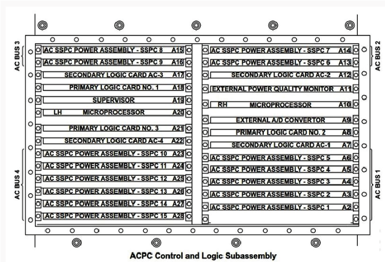
- Swap SSPC 3 (left wing ldg/taxi lights) with SSPC 12 (Right wing ldg/taxi lights). Did the fault transfer over to the other side?
- If YES, replace defective SSPC card and do close out.
- If NO, continue with next step.
- Perform wiring checks between respective landing/taxi light and ACPC. Repair as required.
- Do close out.