

02/21/24
Message Overview:
Message Name:
STORED FAULTS AND SYSTEM DIAGNOSTIC PAGES MISSING FROM CAIMS
| Message Code: | 454OBS001 |
| Effectivity: | All |
| System: | Central Aircraft-Information Maintenance System (CAIMS) |
| System Description: | 45-45-00 - Central Aircraft Information Maintenance System (CAIMS) |
| Schematic Diagram: | [ G5000 ] [ Global Express ] [ Global XRS ] SSM 45-45-00-101 - Central Aircraft-Information Maintenance-System (CAIMS) |
| Wiring Diagram: | [ G5000 ] [ Global Express ] [ Global XRS ] WM 45-45-01-1_001 - Sheet 1 - CAIMS to IAC 1 - ALL [ G5000 ] [ Global Express ] [ Global XRS ] WM 45-45-01-1_001 - Sheet 1 - CAIMS to IAC 1 - [9002-9139] |
Message Description:
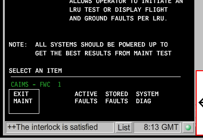
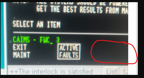
After the Central Aircraft-Information Maintenance System (CAIMS) function starts on the Portable Maintenance-Access Terminal (PMAT), the STORED FAULTS and SYSTEM DIAG pages are not available because there is a problem with the interlocks.
Possible Causes:
- Portable Maintenance Access Terminal (PMAT) (AM-200)
- Junction Box 3 (JB3)
- Integrated Avionics Computer 1 (IAC) (A11)
- Integrated Avionics Computer 2 (IAC) (A10)
- Associated Wiring
Troubleshooting Tips:
Advisory Wire/Service Bulletin: None
Forum Articles/Infoservice/Newsletter: None
Flight Operation Notifications Manual (FONM): None
NOTES:
| Normal Page | Missing Menu |
|---|---|
 |
 |
Quick Links:
| Grounding of the Aircraft | [ G5000 ] [ Global Express ] [ Global XRS ] AMM10-11-00-867-801 |
| Removal of the Covers and Plugs | [ G5000 ] [ Global Express ] [ Global XRS ] AMM10-12-00-020-801 |
| Installation of the Covers and Plugs | [ G5000 ] [ Global Express ] [ Global XRS ] AMM10-12-00-420-801 |
| Standard Aircraft Configuration for Maintenance | [ G5000 ] [ Global Express ] [ Global XRS ] AMM12-00-00-867-801 |
| Aircraft Walkaround (for Maintenance) | [ G5000 ] [ Global Express ] [ Global XRS ] AMM12-00-00-867-802 |
| Connect Electrical Power to the Aircraft | [ G5000 ] [ Global Express ] [ Global XRS ] AMM24-00-00-861-801 |
| Remove the Electrical Power from the Aircraft | [ G5000 ] [ Global Express ] [ Global XRS ] AMM24-00-00-861-802 |
| Electrical/Electronic Safety Precautions | [ G5000 ] [ Global Express ] [ Global XRS ] AMM24-00-00-910-801 |
| Electrostatic Discharge Safety Precautions | [ G5000 ] [ Global Express ] [ Global XRS ] AMM24-00-00-910-802 |
| Removal of the Junction Box JB3 | [ G5000 ] [ Global Express ] [ Global XRS ] AMM24-00-01-000-801 |
| Installation of the Junction Box JB3 | [ G5000 ] [ Global Express ] [ Global XRS ] AMM24-00-01-400-801 |
| Removal of the Junction Box JB3 Circuit-Cards | [ G5000 ] [ Global Express ] [ Global XRS ] AMM24-00-02-000-801 |
| Installation of the Junction Box JB3 Circuit-Cards | [ G5000 ] [ Global Express ] [ Global XRS ] AMM24-00-02-400-801 |
| Removal of the Integrated Avionics Computers (IAC) | [ G5000 ] [ Global Express ] [ Global XRS ] AMM31-41-01-000-801 |
| Installation of the Integrated Avionics Computers (IAC) | [ G5000 ] [ Global Express ] [ Global XRS ] AMM31-41-01-400-801 |
| CAIMS PMAT General Instructions | [ G5000 ] [ Global Express ] [ Global XRS ] AMM45-45-00-970-801 |
| Access to Active Faults | [ G5000 ] [ Global Express ] [ Global XRS ] AMM45-45-00-970-802 |
| Access to Stored Faults | [ G5000 ] [ Global Express ] [ Global XRS ] AMM45-45-00-970-803 |
| Access to System Diagnostics | [ G5000 ] [ Global Express ] [ Global XRS ] AMM45-45-00-970-804 |
| Flight Deck Effect to Fault Correlations | [ G5000 ] [ Global Express ] [ Global XRS ] AMM45-45-00-970-821 |
| PMAT Shutdown | [ G5000 ] [ Global Express ] [ Global XRS ] AMM45-45-01-840-801 |
| Removal of the Portable Maintenance-Access Terminal (PMAT) | [ G5000 ] [ Global Express ] [ Global XRS ] AMM45-45-01-000-801 |
| Installation of the Portable Maintenance-Access Terminal (PMAT) | [ G5000 ] [ Global Express ] [ Global XRS ] AMM45-45-01-400-801 |
| Wire Repair - Maintenance Practices - ALL | [ G5000 ] [ Global Express ] [ Global XRS ] SPM20-12-10-02 |
Troubleshooting Recommendations:
- Make sure the CAIMS interlock conditions are met.
- Aircraft Weight-on-wheels
- Wheel speed less than 50 knots
- Access CAIMS. At the top of the CAIMS window, select "View" and then "Environment Settings". Are both Interlock conditions active (marked with a black dot)?
- If only one of the conditions is not met, troubleshoot the related system (WOW or wheel speed) and do close out.
- If both conditions are met or are not met, continue with next step.
- On the center pedestal reversion control panel, set the SG1 switch to ALTN. Is the fault resolved?
- If NO, go to step 7.
- If YES, continue with next step.
- Remove IAC 1 and Junction Box 3. Perform a continuity check as follows:
From To Result JB3DP1-11F Ground JB3DP1-9G Ground - If there is continuity, repair defective wiring as required and do close out.
- If there is no continuity, continue with next step.
- Perform a continuity check as follows:
From To Result JB3DP1-11F A11AP1-40 JB3DP1-9G A11AP1-41 - If there is no continuity, repair defective wiring as required and do close out.
- If there is continuity, continue with next step.
- Interchange IAC 1 with IAC 2. Is the fault resolved?
- If YES, replace defective IAC and do close out.
- If NO, go to step 11.
- Remove JB3. Access and disconnect PMAT connector P251. Perform a continuity check as follows:
From To Result P251-13 Ground P251-15 Ground - If there is continuity, repair defective wiring as required and do close out.
- If there is no continuity, continue with next step.
- Perform a continuity check as follows:
From To Result P251-13 JB3DP1-11G P251-15 JB3DP1-9H - If there is no continuity, repair defective wiring as required and do close out.
- If there is continuity, continue with next step.
- Remove PCB1 from JB3. Perform a continuity check inside JB3 as follows:
From To Result JB3DJ1-11G Ground JB3DJ1-9H Ground - If there is continuity, replace JB3 and do close out.
- If there is no continuity, continue with next step.
- Perform a continuity check inside JB3 as follows:
From To Result JB3DJ1-11G P1-57 JB3DJ1-9H P1-38 - If there is no continuity, replace JB3 and do close out.
- If there is continuity, continue with next step.
- Replace JB3 PCB1. Is the fault resolved?
- If YES, do close out.
- If NO, continue with next step.
- Replace PMAT.
- Do close out.