07/06/21
Message Overview:
Message Name:
N1 SPEED IS TOO HIGH IN FORWARD THRUST
| Message Code: | 771OBS005 |
| Effectivity: | All |
| System: | Engine Power Indicating System |
| System Description: | 77-10-00 |
| Schematic Diagram: | None |
| Wiring Diagram: | None |
Message Description:
The speed of the N1 Rotor is more than the permitted limits. During Engine operation the N1 Rotor speed is continuously monitored by the Full-Authority Digital Engine Controller (FADEC).
Possible Causes:
- Power Plant
Troubleshooting Tips:
Advisory Wire/Service Bulletin: None
Forum Articles/Infoservice/Newsletter: None
Quick Links:
| Engine Safety Precautions | AMM 71-00-00-910-801 [ Global Express ] [ G5000 ] [ Global XRS ] |
| Dry Motor the Engine | AMM 71-00-00-866-804 [ Global Express ] [ G5000 ] [ Global XRS ] |
| Start the Engine | AMM 71-00-00-866-806 [ Global Express ] [ G5000 ] [ Global XRS ] |
| Operation Limits | AMM 71-00-00-866-807 [ Global Express ] [ G5000 ] [ Global XRS ] |
| Engine Shutdown (Usual) | AMM 71-00-00-866-809 [ Global Express ] [ G5000 ] [ Global XRS ] |
| Removal of the Power Plant | AMM 71-00-00-000-801 [ Global Express ] [ G5000 ] [ Global XRS ] |
| Installation of the Power Plant | AMM 71-00-00-400-801 [ Global Express ] [ G5000 ] [ Global XRS ] |
| Opening of the Cowls | AMM 71-10-00-010-801 [ Global Express ] [ G5000 ] [ Global XRS ] |
| Closing of the Cowls | AMM 71-10-00-410-801 [ Global Express ] [ G5000 ] [ Global XRS ] |
| Detailed Inspection of the LP-Compressor Outlet Guide-Vanes |
AMM 72-32-02-220-801 [ Global Express ] [ G5000 ] [ Global XRS ] |
| Deactivation of the Thrust Reverser (for Maintenance) |
AMM 78-30-00-040-801 [ Global Express ] [ G5000 ] [ Global XRS ] |
| Activation of the Thrust Reverser (for Maintenance) |
AMM 78-30-00-440-801 [ Global Express ] [ G5000 ] [ Global XRS ] |
| Detailed Inspection of the Front-Bearing-Chamber Magnetic Chip-Detector |
AMM 79-21-04-220-801 [ Global Express ] [ G5000 ] [ Global XRS ] |
| Detailed Inspection of the Rear-Bearing-Chamber Magnetic Chip-Detector |
AMM 79-21-04-220-802 [ Global Express ] [ G5000 ] [ Global XRS ] |
| Detailed Inspection of the Accessory-Gearbox Magnetic Chip-Detector |
AMM 79-21-04-220-803 [ Global Express ] [ G5000 ] [ Global XRS ] |
| General Visual Inspection of the LP Compressor Blades | EMM 72-31-02-210-801 [ Global Express ] [ G5000 ] [ Global XRS ] |
| Detailed Inspection of the LP Turbine | EMM 72-50-00-220-801 [ Global Express ] [ G5000 ] [ Global XRS ] |
Troubleshooting Recommendations:
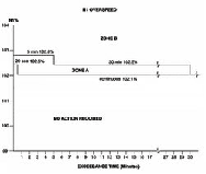
- Perform the fault isolation for the N1 overspeed condition. On the EICAS display system get access to the engine exceedance profile maintenance pages. Record the exceedance profile for N1 rotor speed as follows:
- The maximum speed of the N1 rotor
- The quantity of time that the N1 speed was more than the limit
- If the N1 overspeed was stable or not
- Use the exceedance profile data above and the N1 overspeed limits graph (Figure 1) to find out if the N1 overspeed was in Zone A or Zone B.
- If the N1 overspeed is in Zone B, go to step 16.
- If the N1 overspeed is in Zone A, continue with next step.
- Examine the LP compressor (fan) blades.
- If any damage found, repair the damage as required and do close out.
- If no damage found, continue with next step.
- Examine the LP compressor outlet guide-vanes.
- If any damage found, repair the damage as required and do close out.
- If no damage found, continue with next step.
- Visually examine the stage 2 LP turbine blades.
- If any damage found, repair the damage as required and do close out.
- If no damage found, continue with next step.
- Examine the turbine section fairings for damage.
- If any damage found, repair the damage as required and do close out.
- If no damage found, continue with next step.
- Examine the oil pressure filter element for metal or carbon contamination. Make an analysis of an oil sample for acidity and free carbon content.
- If any contamination found, repair the damage as required and do close out.
- If no contamination found, continue with next step.
- Examine the magnetic chip-detectors for contamination.
- If there is any contamination, repair as required and do close out.
- If there is no contamination, continue with next step.
- Perform the detailed inspection of the front-bearing-chamber magnetic chip-detector.
- If there is a damage, repair as required and do close out.
- If there is no damage, continue with next step.
- Perform the detailed inspection of the rear-bearing-chamber magnetic chip-detector.
- If there is a damage, repair as required and do close out.
- If there is no damage, continue with next step.
- Perform the detailed inspection of the accessory-gearbox magnetic chip-detector
- If there is a damage, repair as required and do close out.
- If there is no damage, continue with next step.
CAUTION: DO NOT USE A TOOL WITH A SHARP EDGE TO TURN THE LP ROTOR. TOOLS WITH SHARP EDGES CAN CAUSE DAMAGE TO THE LP COMPRESSOR BLADES.
- Make sure that the LP rotor can turn freely in a counterclockwise direction (when you look from the front of the engine) without unusual noises.
- If it does not turn freely or there are unusual noises, do not use force to turn the LP rotor. There is possibly internal damage, go to step 16.
- If it turn freely, continue with next step.
- Dry motor the engine. If you hear unusual noises, go to step 16.
- Examine the LP turbine.
- If any damage found, repair the damage as required and do close out.
- If no damage found, continue with next step.
- Perform an engine ground run as follows:
- Start the engine
- Operate the engine to ground idle, and monitor the engine operation limits
- Stop the engine
- Monitor the engine run down time of the LP system
- If the above checks and inspections are satisfactory, put the engine back to usual operation.
- If the above checks and inspections are not satisfactory, refer to your Rolls-Royce representative.
- Replace the power plant.
- Do close out.