07/06/21
Message Overview:
Message Name:
N2 SPEED IS TOO HIGH
| Message Code: | 771OBS008 |
| Effectivity: | All |
| System: | Engine Power Indicating System |
| System Description: | 77-10-00 |
| Schematic Diagram: | None |
| Wiring Diagram: | None |
Message Description:
The speed of the N2 Rotor is more than the permitted limits. During Engine operation the N2 Rotor speed is continuously monitored by the Full-Authority Digital Engine Controller (FADEC).
Possible Causes:
None
Troubleshooting Tips:
Advisory Wire/Service Bulletin: None
Forum Articles/Infoservice/Newsletter: None
Quick Links:
| Engine Safety Precautions | AMM 71-00-00-910-801 [ Global Express ] [ G5000 ] [ Global XRS ] |
| Dry Motor the Engine | AMM 71-00-00-866-804 [ Global Express ] [ G5000 ] [ Global XRS ] |
| Start the Engine | AMM 71-00-00-866-806 [ Global Express ] [ G5000 ] [ Global XRS ] |
| Operation Limits | AMM 71-00-00-866-807 [ Global Express ] [ G5000 ] [ Global XRS ] |
| Engine Shutdown (Usual) | AMM 71-00-00-866-809 [ Global Express ] [ G5000 ] [ Global XRS ] |
| Removal of the Power Plant | AMM 71-00-00-000-801 [ Global Express ] [ G5000 ] [ Global XRS ] |
| Installation of the Power Plant | AMM 71-00-00-400-801 [ Global Express ] [ G5000 ] [ Global XRS ] |
| Opening of the Cowls | AMM 71-10-00-010-801 [ Global Express ] [ G5000 ] [ Global XRS ] |
| Closing of the Cowls | AMM 71-10-00-410-801 [ Global Express ] [ G5000 ] [ Global XRS ] |
| Detailed Inspection of the LP-Compressor Outlet Guide-Vanes | AMM 72-32-02-220-801 [ Global Express ] [ G5000 ] [ Global XRS ] |
| Deactivation of the Thrust Reverser (for Maintenance) | AMM 78-30-00-040-801 [ Global Express ] [ G5000 ] [ Global XRS ] |
| Activation of the Thrust Reverser (for Maintenance) | AMM 78-30-00-440-801 [ Global Express ] [ G5000 ] [ Global XRS ] |
| Detailed Inspection of the Front-Bearing-Chamber Magnetic Chip-Detector |
AMM 79-21-04-220-801 [ Global Express ] [ G5000 ] [ Global XRS ] |
| Detailed Inspection of the Rear-Bearing-Chamber Magnetic Chip-Detector |
AMM 79-21-04-220-802 [ Global Express ] [ G5000 ] [ Global XRS ] |
| Detailed Inspection of the Accessory-Gearbox Magnetic Chip-Detector |
AMM 79-21-04-220-803 [ Global Express ] [ G5000 ] [ Global XRS ] |
| Detailed Inspection of the HP Compressor | EMM 72-33-00-220-801 [ Global Express ] [ G5000 ] [ Global XRS ] |
| Manual Turning of the HP Compressor | EMM 72-33-00-980-801 [ Global Express ] [ G5000 ] [ Global XRS ] |
| Detailed Inspection of the Pressure Filter Element | EMM 79-21-02-220-801 [ Global Express ] [ G5000 ] [ Global XRS ] |
Troubleshooting Recommendations:
Perform the fault isolation for the N2 overspeed condition as follows:
- On the EICAS display system get access to the engine exceedance profile maintenance pages. Record the exceedance profile for N2 rotor speed as follows:
- The maximum speed of the N2 rotor
- The quantity of time that the N2 speed was more than the limit
- If the N2 overspeed was stable or not
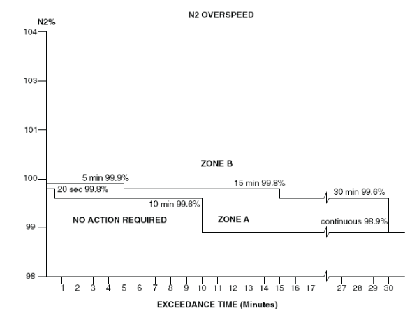
- Use the exceedance profile data and the N2 overspeed limits graph (Figure 1) to find out if the N2 overspeed was in Zone A or Zone B.
- If the N2 overspeed is in Zone B, go to step 11.
- If the N2 overspeed is in Zone A, continue with next step.
- Examine the oil pressure filter element for metal or carbon contamination. Make an analysis of an oil sample for acidity and free carbon content.
- If any contamination or damage found, repair as required and do close out.
- If no contamination or damage found, continue with next step.
- Perform the detailed inspection of the front-bearing-chamber magnetic chip-detector.
- If any contamination found, repair the damage as required and do close out.
- If no contamination found, continue with next step.
- Perform the detailed inspection of the rear-bearing-chamber magnetic chip-detector.
- If any contamination found, repair the damage as required and do close out.
- If no contamination found, continue with next step.
- Perform the detailed inspection of the accessory-gearbox magnetic chip-detector.
- If any contamination found, repair the damage as required and do close out.
- If no contamination found, continue with next step.
- To make sure that the HP rotor can turn freely without unusual noises, turn the HP rotor in a counterclockwise direction (when you look from the front of the engine).
- If it does not turn freely or there are unusual noises, do not use force to turn the HP rotor. There is possibly internal damage. Go to step 11.
- If it turn freely, continue with next step.
- Examine the HP compressor.
- If any damage found, repair the damage as required and do close out.
- If no damage found, continue with next step.
- Examine the HP turbine blades.
- If any damage found, repair the damage as required and do close out.
- If no damage found, continue with next step.
- Perform an engine ground run as follows:
- Start the engine
- Operate the engine to ground idle, and monitor the engine operation limits
- Stop the engine
- Monitor the engine run down time
- If the above checks and inspections are satisfactory, put the engine back to usual operation and do close out.
- If the above checks and inspections are not satisfactory, refer to your Rolls-Royce representative and do close out.
- Replace the power plant.
- Do close out.