07/06/21
Message Overview:
Message Name:
OIL FIRE DETECTION (CHANNEL A) FAILURE
| Message Code: | 772OBS004 |
| Effectivity: | All |
| System: | Oil Fire Detection System |
| System Description: | 77-20-00 |
| Schematic Diagram: | 77-20-00 [ Global Express ] [ G5000 ] [ Global XRS ] |
| Wiring Diagram: | 71-50-01 [ Global Express ] [ G5000 ] [ Global XRS ] |
Message Description:
The fault message is set when there is an open or short circuit in the interface wiring or the Oil Fire-Detection Thermocouple. During Engine operation the Oil Fire-Detection circuits are continuously monitored by the Full-Authority Digital Engine Controller (FADEC).
Possible Causes:
- Oil Fire-Detection Thermocouple
- Engine Electronic Controller (EEC)
- Associated Wiring
Troubleshooting Tips:
Advisory Wire/Service Bulletin: None
Forum Articles/Infoservice/Newsletter: None
Quick Links:
| Engine Safety Precautions | AMM 71-00-00-910-801 [ Global Express ] [ G5000 ] [ Global XRS ] |
| Opening of the Cowls | AMM 71-10-00-010-801 [ Global Express ] [ G5000 ] [ Global XRS ] |
| Closing of the Cowls | AMM 71-10-00-410-801 [ Global Express ] [ G5000 ] [ Global XRS ] |
| Removal of the Bypass-Duct Access Panels (451AL/461AL, 451BL/461BL, 451CL/461CL, 451DL/461DL, 451EL/461EL, 452FR/462FR, 452GR/462GR, 452HR/462HR, 452JR/462JR, 452KR/462KR) |
AMM 72-71-01-000-801 [ Global Express ] [ G5000 ] [ Global XRS ] |
| Installation of the Bypass-Duct Access Panels (451AL/461AL, 451BL/461BL, 451CL/461CL, 451DL/461DL, 451EL/461EL, 452FR/462FR, 452GR/462GR, 452HR/462HR, 452JR/462JR, 452KR/462KR) |
AMM 72-71-01-400-801 [ Global Express ] [ G5000 ] [ Global XRS ] |
| Deactivation of the Thrust Reverser (for Maintenance) | AMM 78-30-00-040-801 [ Global Express ] [ G5000 ] [ Global XRS ] |
| Activation of the Thrust Reverser (for Maintenance) | AMM 78-30-00-440-801 [ Global Express ] [ G5000 ] [ Global XRS ] |
| Removal of the Combustion Section Fairings | EMM 73-03-02-000-801 [ Global Express ] [ G5000 ] [ Global XRS ] |
| Installation of the Combustion Section Fairings | EMM 73-03-02-400-801 [ Global Express ] [ G5000 ] [ Global XRS ] |
| Removal of the Engine Electronic Controller (EEC) | EMM 73-21-01-000-801 [ Global Express ] [ G5000 ] [ Global XRS ] |
| Installation of the Engine Electronic Controller (EEC) | EMM 73-21-01-400-801 [ Global Express ] [ G5000 ] [ Global XRS ] |
| Removal of the Oil Fire Detection Thermocouple | EMM 77-22-01-000-801 [ Global Express ] [ G5000 ] [ Global XRS ] |
| Installation of the Oil Fire Detection Thermocouple | EMM 77-22-01-400-801 [ Global Express ] [ G5000 ] [ Global XRS ] |
| Wire Repair - Maintenance Practices - ALL | SPM 20-12-10-02 [ Global Express ] [ G5000 ] [ Global XRS ] |
Troubleshooting Recommendations:
CAUTION: DO NOT DO ELECTRICAL CHECKS INTO THE ENGINE ELECTRONIC CONTROLLER (EEC). IF YOU DO NOT OBEY THIS INSTRUCTION, DAMAGE TO THE EEC CAN OCCUR.
- Open the circuit breakers that follow:
System Name Circuit Breaker Name Bus Name ENGINE L FADEC CH A BATT ENGINE L FADEC CH B BATT ENGINE L ENG IGN 1 BATT ENGINE L ENG IGN 2 BATT ENGINE L ENG FUEL HPSOV BATT ENGINE L ENG START A BATT ENGINE L ENG START B BATT ENGINE L T/R CTL VALVE BATT ENGINE L T/R LOWER LOCK BATT ENGINE L T/R UPPER LOCK BATT - Perform a deactivation of the thrust reverser.
- Open the cowls.
- Remove the applicable bypass-duct access panel and combustion section fairing.
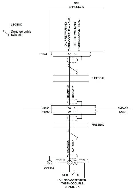
- Examine the interface wiring for damage between the connectors and the terminal blocks that follow:
- The EEC connector P1044
- The bypass duct connectors J1030 and P1030
- The terminal blocks TB2114 and TB2115, and the ground connector GC2106
- The Alumel and Chromel connector posts on the ITT thermocouples
NOTE: Look specially for signs of damage adjacent to clip locations.
- If any damage is found, repair or replace the damage as required and go to step 16.
- If no damage is found, monitor the system to see if the fault message occurs again and continue with next step.
- Check if the fault message is active or not.
- If the fault message is not active, go to step 16.
- If the fault message is active, continue with next step.
- Perform the fault isolation for the ITT signal, disconnect the EEC connector P1044 and the bypass duct connector P1030.
- Disconnect the interface wiring at the terminal blocks TB2114 and TB2115, and at the ground connector GC2106.
- Examine the interface wiring and connectors for damage between the connectors and the terminal blocks that follow:
- The EEC connector P1044
- The bypass duct connectors J1030 and P1030
- The terminal blocks TB2114, TB2115 and ground connector GC2106
- The Alumel and Chromel connector posts on the ITT thermocouples
NOTE: Look specially for signs of chafing adjacent to clip locations, condition of connector pins and wiring kink or strain.
- If any damage is found, repair or replace the damage as required and go to step 16.
- If no damage is found, continue with next step.
- Clean the terminal blocks TB2114, TB2115 and the ground connector GC2103.
- Perform wiring checks between TB2114 and Bypass Duct (P1030).
- If the wiring checks are not good, repair the defective wiring as required and go to step 16.
- If the wiring checks are good, continue with next step.
- Perform wiring checks between TB2115 and Bypass Duct (P1030).
- If the wiring checks are not good, repair the defective wiring as required and go to step 16.
- If the wiring checks are good, continue with next step.
- Perform wiring checks between Bypass Duct (J1030) and EEC (P1044).
- If the wiring checks are not good, repair the defective wiring as required and go to step 16.
- If the wiring checks are good, continue with next step.
- Replace the oil fire-detection thermocouple.
- Install the applicable combustion section fairing and bypass-duct access panel.
- Close the cowls.
- Perform the activation of the thrust reverser.
- Close the circuit breakers that follow:
System Name Circuit Breaker Name Bus Name ENGINE L FADEC CH A BATT ENGINE L FADEC CH B BATT ENGINE L ENG IGN 1 BATT ENGINE L ENG IGN 2 BATT ENGINE L ENG FUEL HPSOV BATT ENGINE L ENG START A BATT ENGINE L ENG START B BATT ENGINE L T/R CTL VALVE BATT ENGINE L T/R LOWER LOCK BATT ENGINE L T/R UPPER LOCK BATT - Make sure that the primary indication of ITT shows on the EICAS display.
- Do close out.